All posts by Avinash

About Avinash

Avinash Gupta is solely focused on free and high quality tutorial to make learning embedded system fun !

Using the USART of AVR Microcontrollers.

Welcome to the third part of my RS232 serial communication tutorial. Till now we saw the basics of RS232 communication and made our level converter. Now its time to understand the USART of AVR microcontroller and write the code to initialize the USART and use it to send and receive data. Like many microcontrollers AVR also has a dedicated hardware for serial communication this part is called the USART – Universal Synchronous Asynchronous Receiver Transmitter. This special hardware make your life as programmer easier. You just have to supply the data you need to transmit and it will do the rest. As you saw serial communication occurs at standard speeds of 9600,19200 bps etc and this speeds are slow compared to the AVR CPUs speed. The advantage of hardware USART is that you just need to write the data to one of the registers of USART and your done, you are free to do other things while USART is transmitting the byte. Also the USART automatically senses the start of transmission of RX line and then inputs the whole byte and when it has the byte it informs you(CPU) to read that data from one of its registers. The USART of AVR is very versatile and can be setup for various different mode as required by your application. In this […]

RS232 Communication – The Level Conversion

Hello and welcome back. Continuing our discussion on RS232 serial communication in this part we will make a RS232 level converter. In the last tutorial we saw that how RS232 level signals differs from normal logic signals. So to interface RS232 level signals to our MCUs we need a "Level converter". And in this tutorial we will make one. What a level converter will do is to convert RS232 level signals (HIGH=-12V LOW=+12V) from PC to TTL level signal (HIGH=+5V LOW=0V) to be fed to MCU and also the opposite. Fig – Working of RS232 level converter       As RS232 is such a common protocol there is a dedicated IC designed for this purpose of "Level Conversion". This IC is MAX232 from Maxim. By using charge pumps it generates high voltages(12V) and negative voltages(-12V). Now lets make it! Things you need S.No Item Value Qty 1 MAX232 IC 1 2 Capacitors 1uF 4 3 10uF 1 4 DB9 Female Connector 1 5 General Purpose PCB 1 6 Some Wires – –   Fig – Stuffs required for RS232 level converter.     Now having all the stuffs in our working table lets begin. The Schematic Fig – Schematic for RS232 level converter.     Assembly Assemble the circuit according to the schematic on a small piece of general […]

RS232 Communication – The Basics

RS232 is a asynchronous serial communication protocol widely used in computers and digital systems. It is called asynchronous because there is no separate synchronizing clock signal as there are in other serial protocols like SPI and I2C. The protocol is such that it automatically synchronize itself. We can use RS232 to easily create a data link between our MCU based projects and standard PC. Excellent example is a commercial Serial PC mouse (not popular these days, I had got one with my old PC which I bought in year 2000 in those days these were famous). You can make a data loggers that reads analog value(such as temperatures or light using proper sensors) using the ADC and send them to PC where a special program written by you shows the data using nice graphs and charts etc.. actually your imagination is the limit! Basics of Serial Communication. In serial communication the whole data unit, say a byte is transmitted one bit at a time. While in parallel transmission the whole data unit, say a byte (8bits) are transmitted at once. Obviously serial transmission requires a single wire while parallel transfer requires as many wires as there are in our data unit. So parallel transfer is used to transfer data within short range (e.g. inside the computer between graphic card and […]

Using IR remote with AVR MCUs – Part II

Hello Friends, Welcome back. In previous tutorial I introduced my IR remote decoding library. In this tutorial I will continue our discussion and show you how to add IR remote controls support to your AVR projects. Step I Download the library files and unzip them in a folder. Step II In AVR studio create a new AVR-GCC project. Then copy the following files to the project folder. IR remote related. Source Files remote.c Header Files remote.h rckeys.h LCD Related Source Files lcd.c Header Files lcd.h myutils.h Note: Include file from the \lib\ATmega8 if you are using ATmega8 \lib\ATmega16 if you are using ATmega16 or ATmega32 After The files have been copied add them to your project by right clicking project view and selecting “Add Existing Source File(s)…” and then select the “lcd.c”. Similarly add other source files. In the same way add the header files by selecting "Add Existing Header File(s)…" Adding files to projects.   If instead of AVR Studio you use Makefiles then add all the source files names in the source section of the makefile along with your main c file (which has same name as your project and has the main function). Step III. In your main C source file include the following files #include "remote.h" in addition to standard files in your main() function initialize […]

Using IR remote with AVR MCUs

Hi Friends, Welcome to my AVR tutorial Series. In this article I will describe my Infrared Remote Control Library. Hope you will enjoy it. I was very much amazed my remote controls since long. The simple circuits described in magazine were just operated like a switch and can only switch on and off an application. That means only single channel. That was of not much use. What I wanted was access to each key on remote control. I wished I could decode the signals generated by common remotes controls found in our homes. This way I could make multi channel remote controls for any project. So I went on and after some web research, coding and debugging I finally succeeded ! Actually I completed that more than one and half year ago (in may 2007). And now I thought I should also make it available to others who are in need of it so that they can use it in their projects. So I went on to make it more "clean" and also to make it more "easily portable" so that it can be used with different devices operating at different frequency. And now the result is here, a very easy to use library that can add remote control feature in any of your AVR project ! Using a IR […]

xBoard™ :: ATmega32 Development Board.

Here are some Videos that demonstrate the xBoard – a easy to use but powerful development system for Atmel AVR ATmega32 microcontrollers. For complete information about the xBoard™ see http://xBoard.eXtremeElectronics.co.in Video #1 xBoard™ :: AVR Dev-Board – Introduction This video tutorial gives you a quick introduction of the xBoard; easy-to-use and powerful Atmel AVR AtMega32 Microcontroller Development Board. Video #2 xBoard™ :: AVR Dev-Board – Hello World In this tutorial we will introduce you to the basic steps needed set-up and develop programs for the xBoard. We’ll write a LED blinking project which is a Hello World project for microcontroller arena. xBoard – a easy-to-use and powerful Atmel AVR AtMega32 Microcontroller Development Board. Video #3 xBoard™ :: AVR Dev-Board – LCD Interfacing This video tutorial teaches you how you can interface a standard 16×2 LCD Module with the xBoard – easy-to-use and powerful Atmel AVR AtMega32 Microcontroller Development Board. Video #4 xBoard™ :: AVR Dev-Board – IR-Remote This video tutorial shows you how to interface a DVD Player Infrared Remote Control with the xBoard, a easy-to-use and powerful Atmel AVR AtMega32 Microcontroller Development Board.

Timers in Compare Mode – Part II

Hello and welcome back to the discussion on the TIMERs in compare mode. In the last article we discussed the basics and the theory about using the timer in compare mode. Now its time to write some practical code and run it in real world. The project we are making is a simple time base which is very useful for other project requiring accurate computation of time like a digital clock or a timer that automatically switches devices at time set by user. You can use it for any project after understanding the basics. We will have three global variable which will hold the millisecond, second and minutes of time elapsed. These variables are automatically updated by the compare match ISR. Look at the figure below to get an idea how this is implemented. Fig – Using AVR Timer to generate 1ms Time base.     Complete Code #include <avr/io.h> #include <avr/interrupt.h> #include "lcd.h" //Global variable for the clock system volatile unsigned int clock_millisecond=0; volatile unsigned char clock_second=0; volatile unsigned char clock_minute=0; main() { //Initialize the LCD Subsystem InitLCD(LS_BLINK); //Clear the display LCDClear(); //Set up the timer1 as described in the //tutorial TCCR1B=(1<<WGM12)|(1<<CS11)|(1<<CS10); OCR1A=250; //Enable the Output Compare A interrupt TIMSK|=(1<<OCIE1A); LCDWriteStringXY(0,0,"Time Base Demo"); LCDWriteStringXY(0,1," : (MM:SS)"); //Enable interrupts globally sei(); //Continuasly display the time while(1) { LCDWriteIntXY(0,1,clock_minute,2); LCDWriteIntXY(3,1,clock_second,2); _delay_loop_2(0); […]

Timers in Compare Mode – Part I

Hi Friends, In last tutorials we discussed about the basics of TIMERs of AVR. In this tutorial we will go a step further and use the timer in compare mode . In our first tutorial on timer we set the clock of the timer using a prescaler and then let the timer run and whenever it overflowed it informed us. This way we computed time. But this has its limitations we cannot compute time very accurately. To make it more accurate we can use the compare mode of the timer. In compare mode we load a register called Output Compare Register with a value of our choice and the timer will compare the current value of timer with that of Output Compare Register continuously and when they match the following things can be configured to happen. A related Output Compare Pin can be made to go high,low or toggle automatically. This mode is ideal for generating square waves of different frequency. It can be used to generate PWM signals used to implement a DAC digital to analog converter which can be used to control the speed of DC motors. Simply generate an interrupt and call our handler. On a compare match we can configure the timer to reset it self to 0. This is called CTC – Clear Timer on […]

Interfacing Temperature Sensor – LM35

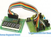
By interfacing different types of sensors with our MCU we can sense the environment and take decisions, in this way we can create "smart" applications. There are wide variety of sensors available. In this tutorial we will learn about a popular sensor LM35 which is precision centigrade temperature sensor. It can be used to measure temperature with accuracy of 0.5 degree centigrade. We can interface it easily with AVR MCUs and can create thermometers, temperature controller, fire alarms etc. Things Required   S. No. Item Image 1 28 PIN AVR Dev Board Contains the core AVR circuit including 5v regulator, reset, ISP. 2 Seven Segment Display Module Four common anode displays multiplexed with driver transistors and current limiting resistors. 3 Single Pin Female to Female Burg Wires Used to interconnect the two boards. And the sensor.   4 USB AVR Programmer To upload the program to the development board. 5 LM35 Temperature Sensor   LM35 LM35 by National Semiconductor is a popular and low cost temperature sensor. It is also easily available. You can buy one from here online. It has three pins as follows. Fig – LM35 Pin Configuration     The Vcc can be from 4V to 20V as specified by the datasheet. To use the sensor simply connect the Vcc to 5V ,GND to Ground and the […]

Multiplexed Seven Segment Displays – Part II

Hi Friends, In last tutorial we discussed about Multiplexing Seven Segment Displays. So you must be very much familiar with the theory. Now let us write the code and design a small project that will make you expert in using these displays in your own projects. We will make a system that can display any number between 0-9999 using four of these displays. We will design a function Print() that we can use on latter projects to easily write integers onto displays. Once we have successfully tested this function we can add to to any project without any problem. This concept of code reuse will make bigger project both easy to make and far less painful. In this sample project we will test our function by using it in a loop to print all numbers from 0-9999. for(i=0;i<10000;i++) { Print(i); Wait(); } Things Required S. No. Item Image 1 28 PIN AVR Dev Board Contains the core AVR circuit including 5v regulator, reset, ISP. 2 Seven Segment Display Module Four common anode displays multiplexed with driver transistors and current limiting resistors. 3 Single Pin Female to Female Burg Wires Used to interconnect the two boards   4 USB AVR Programmer To upload the program to the development board. These are all the things required to get started with seven segment […]

Multiplexed Seven Segment Displays.

We have discussed the basics of seven segment displays on our tutorial “Using Seven Segment Displays with AVR MCUs”. So you should be familiar with them. In this tutorial we will discuss about multiplexing of seven segment displays.Multiplexing is required when we want to interface 3 or 4 or even more such displays with MCUs since it we go for normal way it will require lots of IO port. So the smart way is multiplexing. Multiplexing achieved by tricking our eyes. Only one display is active at a time but we see all of them active. For multiplexing all the displays are connected in parallel such that if you activate any segment, say ‘a’ the ‘a’ segment of all displays glows up. But the trick is that we can switch on and off the “common” line of the displays under MCU control. So if we wish to light up the ‘a’ segment of display 2 we simply switch on display 2 first by applying proper level at the base of its driving transistor as shown in figure. Fig – Multiplexed Seven Segment Displays. If we like to display the digit say “123” on three displays first we select disp-3 by applying a “low” level at the base of transistor Q1 and output the code of required digit at the data […]