All posts by Avinash

About Avinash

Avinash Gupta is solely focused on free and high quality tutorial to make learning embedded system fun !

IIT Guwahati Model United Nations, Techniche

As the journey enters its 16th year, Techniche – the annual techno-management festival of IIT Guwahati is set to write new chapters as they introduce the Model United Nations Conference as one of the highlights of the fest organized in collaboration with UN Information Centre for India and Bhutan. The MUN Conference is a perfect imbiber of all that Techniche seeks to achieve – to ideate innovation, nurture leadership and kindle global insight and aims at promoting the MUN culture in North-East India. Model UN conferences are a simulation of UN conferences and committees. Students take on the roles of diplomats from different countries, representing their nation in discussions and debate on a particular agenda topic in the conference. These agendas reflect issues taken up by the UN for discussion. Delegates must research their allotted countries in great detail, understanding their own foreign policy and thus the considerations and compulsions that determine state behaviour on the international stage. They must also research their committee agenda, fully exploring the intricacies of the issue at hand, including the background, history, its treatment in the UN system, resolutions passed on it, major countries involved, causes, consequences, past action and more. Finally, delegates must research and propose innovative and feasible solutions to the problem, within the framework of the organ or agency they are […]

Introduction to Resistors

Resistors are one of the most basic electronic component. They opposes(or resists) the flow of electric current through them, that is why they are named resistors. This article introduce you to resistors describing how they look, how to measure their value, how to solder them and how to identify them in a schematic. Read more about resistors.  

Microwave Controller using ATmega8 – AVR Project

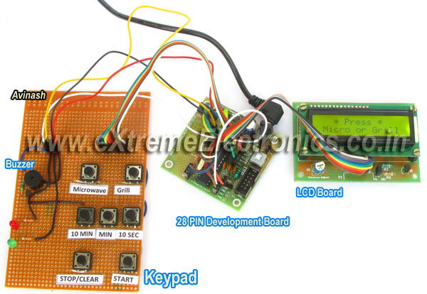
Microwave Controller’s User Interface Fig. Microwave Timer using AVR ATmega8   The user interface has the following parts. Output Device: A 16×2 alphanumeric LCD Module is used as the main output device. It can display numbers, alphabets and few symbols. It can show two line and each line can have 16 characters. The backlight enables the text to be visible even in dark. A buzzer beeps when the system receive input from the user and the input is successfully processed. For example if the user presses 10 MIN button to increment timer by 10 min and this is successfully carried out the buzzer beeps. But if the timer is already at the maximum setting (90 minutes) the operation could be carried out, so the buzzer does not beeps. This buzzer also beeps a few time when the food is ready (countdown is finished) Input Device: Input from user is received by a keypad which has seven push buttons. The details of button is given below. Button Function Microwave Selects Microwave mode. Grill Selects Grill mode. 10 MIN Increment timer by 10 minutes. MIN Increment timer by 1 minute. 10 SEC Increment timer by 1 sec. STOP/Clear If the microwave is in on condition, this button turns it off and pauses the timer count down. If you are setting the timer, […]

Comparing Low Cost AVR Dev Boards

Over the years I have seen people just open up the mouth without thinking. This is more common in the young age group like those of students. Often this also miss leads others. Recently we posted and ad on Facebook for our low cost development board which was priced at Rs. 299. Some guy without thinking a minute, compared it with a even lower cost product from some other vendor. What my point is that those two products are NOT similar ! Their are HUGE differences ! So I thought I should make out those differences stand out. Power Supply Our Board Probots’ Board Has built in 12V to 5V regulator circuit built using 7805 IC. No regulator. Advantage   You can power up the board using an adapter of any voltage output between 9v to 18v Using higher voltage adapter has the advantage that power from it can be used to driver higher voltage devices like relays or motors. You can power up using a 5v adapter only! If you need 12v supply to power relays or motors you need a separate adapter or battery.   Power Switch Our Board Probots’ Board Has an on/off switch No on/off switch Advantage   Easy power control. Frustration on long run.   Prototyping Area Our Board Probots’ Board Has large prototyping area […]

ATmega8 HC-SR04 Ultrasonic Sensor Interface Demo

Ultrasonic Rangefinder HC-SR04 Interfacing with ATmega8

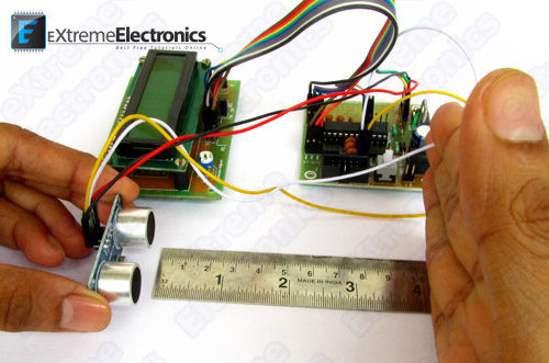
In this article I will describe how to interface a Ultrasonic Range Finder Module with a AVR ATmega8 microcontroller. I will provide a HEX file which you can burn into your ATmega8 directly to quickly test this whole setup. Ultrasonic range finder modules helps find the exact distance to an object. This can have vast application in robotics. These are more expensive than IR based obstacle detectors but the advantage is that they give accurate distance to the obstacle and also their performance is not affected by the colour of obstacle. Ultrasonic Range Finder HC-SR04   Things Required   S. No. Item Image 1 28 PIN AVR Dev Board Contains the core AVR circuit including 5v regulator, reset, ISP. 2 16×2 LCD Board Alphanumeric LCD Module subsystem on board. 3 Single Pin Female to Female Burg Wires Used to interconnect the two boards. And the sensor.   4 USB AVR Programmer To upload the program to the development board. 5 Ultrasonic Range Finder Module 6   12V 1A Power Adapter.   Connect LCD Board Please read this article on interfacing alphanumeric lcd module with AVR microcontrollers. Interfacing LCD Modules with AVR Connect the LCD Board with the development board using single pin f/f burg wires according to the table given below.   LCD Board AVR Dev Board   1 R/W […]

PIC16F877A Serial Communication Demo

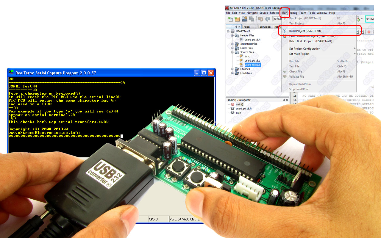
In the last two tutorial we discussed how to make the hardware for serial communication and how to setup a MPLABX Project with support for serial communication functions. Then we complied a demo program to use those serial communication functions and burnt the final hex file to our PIC16F877A development board. Now its time for us to run this demo. Setting up hardware for PIC Serial Communication USART Library for PIC – Setup on MPLAB X IDE To interact with this demo running on your PIC development board. You need a terminal program. A terminal program is a utility tool running on PC that helps you view text data coming from the serial port and also send data to the port. This is handy for initial development of connected hardwares. We use Real Term for this purpose. You can download it from here. Download Real Term. RealTerm The top black area show the character data as they are received by the serial port. The received characters are shown in YELLOW coloured text. The bottom area has lots of tab on it. The Port tab (shown above) is used to configure the serial port. Configure the port exactly as show in the image above. Baud = 9600 Port = <the serial port number where you have connect the PIC development board> […]

USART Library for PIC – Setup on MPLAB X IDE

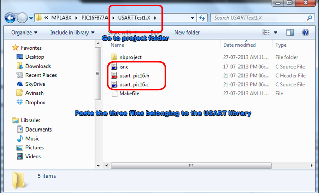
This article describes the setup and use of the C library for serial communication. We focus on its usage with PIC16F series of MCUs from Microchip. Here we describe how to setup a MPLAB X project with support for serial communication related functions. The library is designed for compilation and use with Microchip’s XC8 C Compiler. Fig. Serial Communication Demo   Creating a New Project in MPLAB X You can create a new project using the MPLAB’s Start page as shown below. Fig. MPLAB X Start Page Alternatively you can use menu File->New Project Fig. Select New Project from File Menu And for those who love the Keyboard over mouse can hit <Ctrl>+<Shift>+<N> Any of the three method will launch the New Project Wizard as shown below. The first step is the selection of project type. From the Categories list select Microchip Embedded and from Projects select Standalone Project. Fig. Project Type Selection Second step is the selection of device for which the project is targeted. Select Mid Range 8-bit MCUs (PIC12/16/MCP) in Family and PIC16F877A in Device. Fig. Device Selection Third step is the selection of debug tool. For that select Simulator. Fig. Tool Selection Microchip MPLAB lets you install more that one compiler. It also lets you install more that one version of the same compiler. So their […]

Serial Communication with PIC16F877A

This article series aims at teaching serial communication between a PIC microcontroller and a PC. We first introduce you with what is serial communication is and how it can used. Then we tell you how to perform serial communication using PIC microcontroller and how we use the USART peripheral for the purpose. We will tell you how our usart library for PIC16F series can be used for easy serial communication, in this part we also discuss how to set up a MPLAB X project for using the USART library. After that we will build a demo project to explore the library. Finally we will burn this demo in a PIC16F877A and establish a serial communication with PC. Serial Communication Their are several serial communication standards like RS232, SPI, I2C etc. Of which RS232 is a asynchronous method. That means it does NOT have a synchronizing clock line. One way data requires only one conductor line. Since it is a two way communication their are two lines between the two device. One for sending data called the Tx and one for receiving data called the Rx. The communication is full duplex, that means data can be sent at the same time data is being received. generally other serial communication like SPI and I2C are used for short range communication like between […]

Making A Thermometer with PIC16F877A

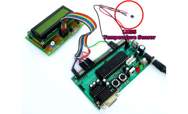
At basic level on microcontroller you can create this interesting project of digital thermometer. It teaches you how to acquire analog data from a sensor and display it on a lcd. We will use a popular MCU PIC16F877A to implement this mini project. The temperature will be read using a LM35 precision sensor. Final result will be shown on a 16×2 alphanumeric lcd module. Fig. PIC16F877A Based Thermometer with LCD   Stuffs Required S. No. Item Image Cost 1 40 PIN PIC Development Board Rs. 769 2 16×2 LCD Board Rs. 296 3 Single PIN Burg Wires Female/Female 20 units Rs. 100 4 12V 1A DC Adapter Rs. 127 5 LM35 Rs. 60     Total Rs. 1,352 Connections The PIC16F877A development board has the PIC16F877A microcontroller chip and its supporting basic circuitry all in a nice high quality PCB. The development board comes fully assembled and tested, thus makes it ideal for doing experiments for learning by beginners. 40 PIN PIC Development Board In the bottom portion of the pic development board you can see a row of male headers. Most of these pins are the microcontrollers general purpose input/output lines and the rest are 5v and GND supply lines. Using these pins you can connect external peripherals (like the LCD board or something else) to do your experiment. […]

LCD Library for PIC – Setup on MPLAB X IDE

This article describes the setup and use of the C library for hd44780 based alphanumeric lcd modules. This library is also available for the AVR family of microcontrollers. This part is focused on its usage with PIC16F series of MCUs from Microchip. Here we describe how to setup a MPLAB X project with support for lcd related functions. The library is designed for compilation and use with Microchip’s XC8 C Compiler. Fig. LCD Demo   Creating a New Project in MPLAB X You can create a new project using the MPLAB’s Start page as shown below. Fig. MPLAB X Start Page Alternatively you can use File->New Project Fig. Select New Project from File Menu And for those who love the Keyboard over mouse can hit <Ctrl>+<Shift>+<N> Any of the three method will launch the New Project Wizard as shown below. The first step is the selection of project type. From the Categories list select Microchip Embedded and from Projects select Standalone Project. Fig. Project Type Selection Second step is the selection of device for which the project is targeted. Select Mid Range 8-bit MCUs (PIC12/16/MCP) in Family and PIC16F877A in Device. Fig. Device Selection Third step is the selection of debug tool. For that select Simulator. Fig. Tool Selection Microchip MPLAB lets you install more that one compiler. It also […]

LCD Module Interface with PIC16F877A

This article describe the hardware setup required for interfacing HD44780 based alphanumeric LCD modules with a PIC16F877A microcontroller. The software part consisting of the LCD library for PIC, its setup and use with MPLAB X IDE and XC8 compiler are described in a separate article. LCD Library for PIC – Setup on MPLAB X IDE A common controller chip used in many alphanumeric LCD module is the HD44780. The purpose of the controller is to generate pixel patterns and drive individual pixels of the LCD to show characters and symbols. In this method the main microcontroller running your application code does NOT need to generate the pixel patterns, it just need to tell the controller chip which character or symbol to show the rest is done by the controller, i.e. the HD44780. The same controller chip is used in many differently sized alphanumeric LCDs. Thus the connection schematic and driving code is same. Pin Details of LCD Module All HD44780 based LCD modules have 16 pin connecters. The detail about these pins is given below. Interface pins of LCD Module   Pin Number Pin Name Pin Type Connected with PIC16F877A’s pin 1 VSS Power Supply – 2 VCC Power Supply – 3 VEE Contrast Adjust – 4 RS Control Line RD4 5 R/W Control Line RD5 6 E Control Line […]

Getting Started with AVR Microcontrollers

The first step in getting started with microcontrollers is to choose a microcontroller family to work with. Their are hundreds different microcontroller families from many different manufactures. Selecting a Microcontroller There are two family of microcontroller that are extremely popular among hobbyist. The “PIC” series from Microchip and “AVR” series from Atmel. Both these chips are wonder of modern microelectronics. PIC had ruled for a long time but now AVR is also getting in serious competition. Speed and ease of use. I prefer AVRs because one major reason. They are fast. When a PIC and an AVR is running with same frequency lets say 16 MHz, then the AVR is actually executing four times faster than the PIC ! Yes 4 times faster. This is because the PIC requires 4 cycle to perform a single execute cycle while the AVR execute most of the instruction in 1 clock cycle. In addition, I like the AVR architecture because of its consistency. It makes using the most advanced feature of AVR very easy to use. These chips are easily available and they are cheap. Free “C” compiler. One more important thing, generally microcontroller programs are written in assembly language for efficiency. Which you may know is a very low level and unstructured language. Therefore, to achieve a small thing lots of code […]