Hello Friends,
In this tutorial we will make a "Digital Stop Watch" using an AVR ATmega8 Microcontroller. This will help you learn many concepts like
- Multiplexed Seven Segment Display Interfacing
- Using AVR Timers
- Using Interrupts
- And many others too.
The code is written in C language for avr-gcc (WinAVR) .
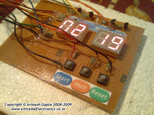 |
Fig.: Digital Stop Watch Prototype |
Steps to Build the "Digital Stop Watch" using AVR ATmega8 MCU
- Make the circuit according to the schematic on general purpose PCB or a BreadBoard.
- Make a project in AVR Studio and add a new file to the project. Copy/paste the "c" code. Set optimization as "o2" and CPU frequency as 16000000Hz. Save and Build the project. You will get a HEX file.
- Burn this HEX file to an ATmega8 MCU using a tool such as eXtreme Burner AVR.
- Set High Fuse = C9(Hex) Low Fuse = FF(Hex). How to do this depends on you programmer software.
I have use a xBoard MINI development board for fast and easy prototyping. The Displays+Transistors+Key are on the Veroboard while the Core CPU unit + power supply is in the xBoard MINI. It can be programmed "In System" over USB Port using eXtreme Burner – AVR software toolkit.
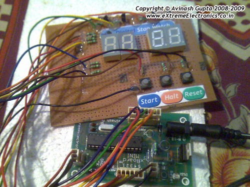 |
Fig.: Digital Stop Watch made using xBoard MINI |
How to Use the "Digital Stop Watch"
When initially powered up the Stop watch is in "STOP" condition. This is indicated by a blinking display. The count is 00:00 initially. Press "START" to start the watch. The blinking will now stop and the display will be fully on. It will start counting and MIN:SEC is displayed. The stop watch can be halted at any time by pressing "HALT" key. In halt state the counting freezes and the display starts blinking. You can press "START’ key again to resume counting from there. The "RESET" key is used to reset the clock to 00:00 i.e. 0 minute and 0 sec.
Digital Stop Watch Schematic
 |
Fig.: Digital Stop Watch Schematic |
Digital Stop Watch C Source Code.
/*

Description:   An AVR ATmega8 based Digital Stop Watch

            Project.
________________________________________________________

Author:  Avinash Gupta
Date: 04 July 09
Web      www.eXtremeElectronics.co.in


*/

#include <avr/io.h>
#include <avr/interrupt.h>
#include <util/delay_basic.h>

#define true 1
#define false 0

#define SEVEN_SEGMENT_PORT PORTD

#define SEVEN_SEGMENT_DDR DDRD

volatile uint8_t digits[4];

//Global variable for the clock system
volatile unsigned int   clock_millisecond=0;
volatile unsigned char  clock_second=0;

volatile unsigned char  clock_minute=0;
volatile unsigned char  clock_hour=0;

//Display hiding system
uint8_t hide_display = false;

//Blinking system

uint8_t blink_display = true;


void SevenSegment(uint8_t n,uint8_t dp)
{
/*
This function writes a digits given by n to the display
the decimal point is displayed if dp=1

Note:
n must be less than 9

*/
   if(n<11)
   {
      switch (n)
      {
         case 0:
         SEVEN_SEGMENT_PORT=0b00000011;
         break;

         case 1:
         SEVEN_SEGMENT_PORT=0b10011111;
         break;

         case 2:
         SEVEN_SEGMENT_PORT=0b00100101;
         break;

         case 3:
         SEVEN_SEGMENT_PORT=0b00001101;
         break;

         case 4:
         SEVEN_SEGMENT_PORT=0b10011001;
         break;

         case 5:
         SEVEN_SEGMENT_PORT=0b01001001;
         break;

         case 6:
         SEVEN_SEGMENT_PORT=0b01000001;
         break;

         case 7:
         SEVEN_SEGMENT_PORT=0b00011111;
         break;

         case 8:
         SEVEN_SEGMENT_PORT=0b00000001;
         break;

         case 9:
         SEVEN_SEGMENT_PORT=0b00001001;
         break;

         case 10:
         //A BLANK DISPLAY

         SEVEN_SEGMENT_PORT=0b11111111;
         break;

      }
      if(dp)
      {
         //if decimal point should be displayed
         //make 0th bit Low
         SEVEN_SEGMENT_PORT&=0b11111110;
      }
   }
   else

   {
      //This symbol on display tells that n was greater than 10
      //so display can't handle it
      SEVEN_SEGMENT_PORT=0b11111101;
   }
}

void Wait()
{
   uint8_t i;
   for(i=0;i<10;i++)
   {
      _delay_loop_2(0);
   }
}


void Print(uint16_t num)
{
   /*

   This function breaks apart a given integer into separete digits
   and writes them to the display array i.e. digits[]

   */

   uint8_t i=0;
   uint8_t j;
   if(num>9999) return;


   while(num)
   {
      digits[i]=num%10;
      i++;

      num=num/10;
   }

   //Fill with leading 0s

   for(j=i;j<4;j++) digits[j]=0;
}


void main()
{
   uint16_t i;

   // Prescaler = FCPU/1024
   TCCR0|=(1<<CS02);

   //Enable Overflow Interrupt Enable

   TIMSK|=(1<<TOIE0);

   //Initialize Counter
   TCNT0=0;

   //Port c[3,2,1,0] as out put
   DDRC|=0b00001111;

   PORTC=0b00001110;

   //Port D

   SEVEN_SEGMENT_DDR=0XFF;

   //Turn off all segments
   SEVEN_SEGMENT_PORT=0XFF;

   //Set up the timer1 as described in the
      //tutorial
      //TCCR1B=(1<<WGM12)|(1<<CS11)|(1<<CS10);

   //initailly stop the timer by setting clock source =000
   TCCR1B&=(~((1<<CS12)|(1<<CS11)|(1<<CS10)));
      OCR1A=250;

      //Enable the Output Compare A interrupt
      TIMSK|=(1<<OCIE1A);

      //Enable interrupts globally

      sei();

      //Continuasly display the time
      while(1)
      {
         int disp;
      disp=(clock_hour*100)+clock_minute;
      //disp=(clock_minute*100)+clock_second;

      Print(disp);

      if(!(PINB & (1<<PB2)))
      {
         //RESET PRESSED
         clock_millisecond=0;
         clock_second=0;
         clock_minute=0;
         clock_hour=0;
      }

      if(!(PINB & (1<<PB1)))
      {
         //halt pressed

         //stop the timer
         TCCR1B&=(~((1<<CS12)|(1<<CS11)|(1<<CS10)));

         //Start blinking the display
         blink_display=true;
      }

      if(!(PINB & (1<<PB0)))
      {
         //start pressed

         //start the timer
         //Set up the timer1 as described in the
            //tutorial
            TCCR1B=(1<<WGM12)|(1<<CS11)|(1<<CS10);

         //Stop blinking the display

         blink_display=false;

         //Show the display
         hide_display=false;
      }

         _delay_loop_2(0);
      _delay_loop_2(0);

      }


}

ISR(TIMER0_OVF_vect)
{


   /*

   This interrup service routine (ISR)
   Updates the displays

   */
   static uint8_t i=0;

   if(i==3)
   {
      //If on last display then come

      //back to first.
      i=0;
   }
   else
   {
      //Goto Next display
      i++;
   }

   //Acivate a display according to i

   PORTC=~(1<<i);

   if(hide_display)
   {
      //Show a blank display
      SevenSegment(10,0);

   }
   else
   {
      //Write the digit[i] in the ith display.

      SevenSegment(digits[i],0);
   }

   //Handle blinking

   if(!blink_display) return;

   static uint8_t blink_counter=0;

   blink_counter++;
   if(blink_counter == 16)
   {
      blink_counter =0;

      hide_display=!hide_display;
   }

}


//The output compate interrupt handler
//We set up the timer in such a way that
//this ISR is called exactly at 1ms interval
ISR(TIMER1_COMPA_vect)
{
      clock_millisecond++;
      if(clock_millisecond==1000)
      {
      clock_second++;
         clock_millisecond=0;
         if(clock_second==60)
         {
            clock_minute++;
            clock_second=0;
         }
      if(clock_minute==60)
      {
         clock_hour++;
         clock_minute=0;
      }
      }
}
Downloads
- Schematic in PDF format.
- Schematic in GIF format.
- C Source Code
- HEX Code ready to burn
- AVR Studio Project as ZIP file
Project Video
Facing problem with your embedded, electronics or robotics project? We are here to help!
Post a help request.
Avinash
Avinash Gupta is solely focused on free and high quality tutorial to make learning embedded system fun !
Follow Me:


Very good project for beginner.
Please put a tutorial/project on mmc interfacing with atmega 16/32 on you website.
can you give me the design file at saifbd3@gmail.com? I can’t do this design.
Thanks.
Your programs are tough to understand for the beginners as it contains many complex terms please make them less complex as you can.
I am not criticizing your work, you did very good job but the terms like uint8_t and functions makes a lot of maggi in mind so please demontrate them clearly.
@Ashutosh,
uint8_t is “UNSIGNED 8 BIT INTEGER” and its a typedef for unsigned char
Now don’t ask whats a typedef or why instead of unsigned char we are writing uint8_t.
Also uint8_t (and its many other varrients like UINT8,UINT16,UINT32) is as common in C/C++ programming (including libraries such as Windows API, gnome gtk/gtk+, MFC etc) as “if” statement or “while” loop in ANY PROGRAMMING LANGUAGE.
One thing I notice in novice is that they try to make “C” programming more “Amateurish” than “Professional” . “C/C++” is a very “Professional” language and its features are somewhat “confusing” if seen from a Amateurs perspective. If you don’t like it switch to “BASIC”
Progran written is very good for beginners , i like the way u have explained , it is really good, expect lot of more projects from you
hi,
very nice project at first.
i wanted to ask about a fuses. do i have to write “C9(Hex)” or just “C9” in a high fuse field?
thanks.
JUST WRITE C9. C9(HEX) MEAN IT IS IN HEXADECIMAL NUMBER.
how to do this with lcd
Hi,
good job !
I’ve just a question about it, what’s the effect of pressing start DURING the counting ?
Thanks
TRY AND SEE.
hi sir,the project is superb can you give me its working discription,its urgent
Hi,
Ashutosh im from varanasi give a call on my
personal celll no. it’s urgent 09793280001 / 09839148488
thanks awaitng for ur reply
Hellow brother nice work, keep it up
m a cs student n not so much familiar with the electronic circuits
plz tell the meaning of those arrows from Q1,Q2,Q3,Q4
similarly R14,15,16 and R12 and r13
Aref
vcc
do i have to connect them all from r13???
plz reply as soon as possible i have to submit my project in a couple of days
@Waqas,
Brother, they are symbol for Vcc, in our case the Vcc is 5v coming from the 7805 IC (U2)
Simply it means all arrows are connected.
In the same way all GNDs are connected. Hope you can figure out the ground (GND) symbols.
Thanks
thnx for ur response
i tried to make this circuit on Proteus i made all the connections,for atmega8 i uploaded ur hex file
still the circuit is not working
1st i tried the same procedure like i inserted same arrows then i connected them from the Vcc coming frm U2
but still didnt work :s
plz help me out
brother can u plz send me this circuit designed on proteus?? ill b thankfull
my id is gr8_wiqqi@hotmail.com
i dunt know y they teach us electronix n controllers :sss urghhhh its non of our concern :@
can you write the code in assembly, cause i am new to this and i found it a little challenging for my first project.
thanks
Can you please make a flowchart for this program and send it to my email ID I’ll be thankfull of you.
can v create a stop watch in which the output comes out of the form m m:s s:ms ms???
OF CAUSE U CAN CREATE ………DO IT UR SELF…GOOD LUCK.
thanks & gud work bro……helped me build digital clock with timer …. have uploaded it in ma blog…..
http://goavr.blogspot.in/p/digital-clock-with-timer-thermometer.html
hey I need the assembly code for the project
Ashok,code is written in C language.Assembly code is not available for this project.
hey how to make the hardware part..am new to microcontroller.. help me out..
nice work.I need ur help. I want to reset and restart digital watch using a same switch as I want to display digital watch.Here is my code:
if(!(PINB & (1<<PB4)))
{
TCCR1B=(1<<WGM12)|(1<<CS11)|(1<<CS10);
}
else
{
clock_millisecond=0;
second=0;
minute=0;
hour=0;
TCCR1B=(1<<WGM12)|(1<<CS11)|(1<<CS10);
}
Here in if condition first clock is incrementing its value but in else statement the clock is set to 0 and second clock is not incrementing its value.Please help i want to increment both clock after resetting it to 0 using a single switch.Plz help
sir, can i use this code for atmega32.
will it work ?
if yes, then what changes i have to made in the program ?
plz help me out
first learn how to spell “please”
sorry
please help me out sir
@Pranab
Your question “can i use your digital stop watch code of atmega8 in atmega32 ? will it work ? ”
The answer is NO, it will not work on ATmega32
but sir both are 8bit microcontroller.
And alternate functions of the ports of atmega8 and atmega32 are almost the same, only the pin numbers differ.
can this code be modified to use in atmega32 ?
could you please help me with the code.
Hi! Nice tutorial, but I have an issue.. I programmed C9 DF instead of C9 FF because I wanted to be able to programm atmega8 with ISP using http://dx.com/p/usbasp-usbisp-downloader-programmer-for-51-avr-157167
however, it is not working and it is impossible to program again even with 4Mhz XTAL and 2x 16pF capacitors. Should I be able to program atmega again witch XTAL at 16Mhz and capacitrs 22pF, witch mentioned device?
THX. Lukas.
Solved! ATmega restored by http://mightyohm.com/blog/2008/09/arduino-based-avr-high-voltage-programmer/
Good afternoon
I made this project as an exercise in making pcb’s and circuits up.
I had to use your hex file as I don’t begin to understand the coding side .
Now it all seemed to check out BUT I think I have the wrong displays I have common cathode and I can (now) see your are common anode.
My theory is I swap the pnp for npn transistors but I have no idea where to begin with altering the “code”… I am happy to experiment and get a compiler etc but can you point me in the right direction re what code to change.
sorry if this is too basic but my old brain struggles more each day
Thank you
John
sir ., i purchased 7-seg module from http://store.extremeelectronics.co.in/Seven-Segment-Module.html ( COMMON CATHODE ) …, but your are using COMMON ANODE in this project …, what are the changes should i make in the program …???
Please can I get the Schematic design for PIC16F84A
Same circuit requirement ( 3 switches START,STOP AND RESET)
Please can you attach the code also
Thanks
sir, can I ask you.. how to program PIC18F4520 stop watch.
Hello sir, thank for this project, i buid this and work ok with yor hex file but please can help me to stop blinking on pause or blinking with lower freqency? I try to compile in avr studio 5 but i can’t put : “Set optimization as “o2″ and CPU frequency as 16000000Hz” and the clock work verry slowly .
Thank you !
@Mircea,
Yes I will send you a modified HEX file. But first please send your selfie along with the project.
Hello sir Avinash ! Thank you for your answer, i didn’t understand what i must put but if need a picture of my project i tray to upload one, see teh breadboard and also pcb ready for components , i need hex with slow frequency blink on pause pls send to mirceacra@gmail.com
[url=https://postimg.org/image/vak1l752t/][img]https://s10.postimg.org/vak1l752t/20160326_180934.jpg[/img][/url]