A digital device like a microcontroller can easily work with inputs and outputs that has only two state, on and off. So you can easily use it to control a LED’s state i.e. on or off. In the same way you can use it to control any electrical device on/off by using proper drivers (transistor,triac, relays etc). But sometimes you need more than just "on" & "off " control over the device. Like if you wanna control the brightness of a LED (or any lamp) or the speed of DC motor then digital (on/off) signals simply can’t do it. This situation is very smartly handled by a technique called PWM or Pulse Width Modulation.
PWM is the technique used to generate analogue signals from a digital device like a MCU. Almost all modern MCUs have dedicated hardware for PWM signal generation. In this tutorial we will learn the basics of PWM technique and later on we will see how to implement PWM generation with AVR microcontrollers.
PWM : Pulse Width Modulation
A digital device, like a microcontroller can only generate two levels on its output lines, HIGH=5v and LOW=0V. But what if we want to generate 2.5v or 3.1v or any voltage between 0-5 volt output ? For these kinds of requirement, instead of generating a constant DC voltage output we generate a square wave, which has high = 5V and Low = 0v (See figure 1).
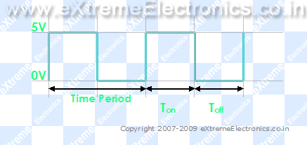 |
Fig. 1 – A PWM Waveform. |
|
In the figure you can see a PWM signal. As you can see it is just a digital signal (can easily be generated by MCUs). But let me clarify some of its properties.
- The signal remains "ON" for some time and "OFF" for some time.
- Ton = Time the output remains high.
- Toff = Time the output remains Low.
- When output is high the voltage is 5v’
- When output is low the voltage is 0v
- T = Time Period = Ton + Toff
Duty Cycle.
It is defined by
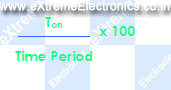
So you can see it is just the percentage of the total time the output was high. In the above figure (Fig. 1) you can see that Ton = Toff = Half of the time period. So the duty cycle is 50%. If the frequency of such wave is sufficiently high (say 500 Hz) the output you get is half of 5v i.e. 2.5 volts. Thus if this output is connected to a motor(by means of suitable drivers) it will run at 50% of its full speed at 5v. The PWM technique utilizes this fact to generate any voltage between two extremes (for example between 0-12volts). The trick is to vary the duty cycle between 0-100% and get same percentage of input voltage to output. Below are some examples of PWM signals of different duty cycle.
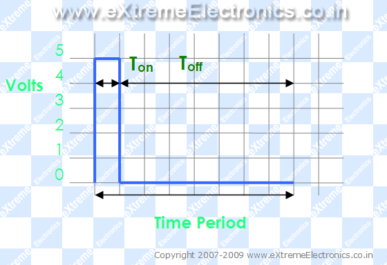 |
Fig. 2- A PWM Waveform. Duty Cycle = 12.5% Analog Voltage Out = 12.5% of Vcc (5v) = 0.625 Volts |
|
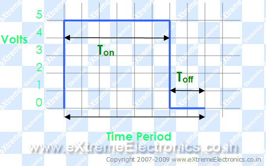 |
Fig. 3- A PWM Waveform. Duty Cycle = 75% Analog Voltage Out = 75% of Vcc (5v) = 3.75 Volts |
|
So you just saw how we can generate analog voltage levels from a digital system using PWM technique. If the output is provided with an R/C filter you will get a pure DC signals levels instead of square waves. But this isn’t required for driving motors or controlling LED’s brightness. You can feed the PWM signals directly to then (by directly I mean without the R/C filter and not the drivers (like transistor etc)).
In the next tutorial we will see how to actually generate PWM signals from an AVR MCU. Till then good bye. But don’t forget to leave your comment ! May be you have some doubts, request or any feedback, feel free to say !
Pingback: PWM Signal Generation by Using AVR Timers. | eXtreme Electronics
Pingback: PWM Signal Generation using AVR Timers | eXtreme Electronics
Hi Avinash,
Do you have any suggestions about how this might be applied to decoding infra-red protocols?
Cheers,
Paul
Hello Paul,
🙂
For IR decoding see
https://extremeelectronics.co.in/category/code-libraries/
nice the author seems to be doing a very nice job
thanks for putting up the info, you have great tutorials. they are short and have just enough info not to complicate noobs! great work and thank you again for sharing!
the above text was really helpful…
its quite helpful……
Hey, i am using a dsp for my project. Can you pls help me by showing me how to generate a PWM for a DSP 56F807.
Thanks
Hi Avinash,
Thanks a lot .
Actually becoz of ur tutorials i came to know the clear clarification regarding PWM.its helped me so much.
And wishing u a very bright future.
really good tutorial
thx a lot
really helped
thanx for tutorial it really helped me
quite helpful tutorials…thanx
simply the best…
awesome tutorial …nice illustration of examples .
@Poru,
Thanks ! Glad you all are loving it ! 🙂
Pingback: Sound Generation by AVR Micro - Tutorial I | eXtreme Electronics
Let’s say that we have a frequency of 1 Hz which means 1 cycle per second and a duty cycle of 50%.
At this low frequency, our LED will turn half a second ON and half OFF, but at maximum light intensity !?
If I’m right, then the frequency it’s very important as a parameter of the waveform.
Your doing a good job! Thanks!
And what happens if we have a very very big frequency?
Is the LED always be ON, at max intensity?
I got a project i.e to control the light intensity of Leds with the help of 89c52. i have no idea about that. your tutorial is good but not enough for me, can you give me detail of this(programming etc. plz help me
Hey,
your tutorials are really good. I was really confused about many things related to AVR and PWM. your website is seriously awesome! keep up the good work!
Pingback: Servo Motor Control by Using AVR ATmega32 Microcontroller | eXtreme Electronics
thanx a lot u man
avobe thing are quit use ful
thanks alot man.really help me in my study.
awesome
do we have to use RC filter, if output of MCU is connected to computer speaker to hear the sound produced?
@Kishan,
Well, Yes and No. I have connected the sound produced using PWM technique to PC speaker (powered) directly. You may also connect via a 4KHz low pass passive r/c filter
Can you explain TCR1/TCR2 and TCCR in 8535.
Thanks a lot of..
see..U..
big thanks to u for giving to this type of material.
@Murali,
Thanks!!!!
Thanks a lot buddy!!
Keep up the gud work!! 🙂
Lucid and to the point explanation. You will definitely go distances as far as your career graph is concerned.
really help full to learners ThankYou
Pingback: AVR Project – ATmega8 Based Smart Code Lock | eXtreme Electronics
This is a very good presentation. Thanks!
very simple.. but effective! good work
Describes very easy to understand. Thank you. Sometimes, If explain too much, it is hard to get it.
An excellent intro to PWM. Thanks for the good work.
Pingback: PWM Signal Generation using AVR Timers | Priyank
Pingback: How to ajust light of LEDs using PIC16F877 PWM (HiTech C)
Thanks a lot…
Though i’m new in AVR,but i’ve get some basic knowledge about PWM. I hope will get more help the basic idea from
other tutorial.
thanks again. 🙂
H!,
Thankx for sharing and it is really helfull
H!,
Thankx for sharing and it is really helpfull
Great work, every information is easy to understand and implement
A very nice explanation for learners..
Thanks a lot…
Explanation is simple and easy to understand, i hope the author will add some more new topics.
thanks a lot…
Explanation is simple and easy to understand, i hope the author will add some more new topics of this kind.
thanks a lot…
Thank You!
This is a very beautiful tutorial.The language is simplified.
thanx a lot… it was very effective.esp. the example made me more clear about PWM.
Hi..
Really a very good tutorial..
Thanks..
how can pwm be related to communication ?
i.e. once you have generated square wave then except for LED dimness and battery charging, how can you put it in use to some communication related application or directly in communication ?
please reply ASAP.
thank u
Avinash,
Thank you very much. You are doing a great job.
I just took up electronics as a hobby and I am really grateful I found out your tutorials.
They have been a lot of help.
God bless you.
rmore.
@Rmore
Thanks
@Avinash, thanks for a great tutorial . can u tell me that how can i change the bootloader of atmega16 or if you have any tutorial , please snd me link……
Thank you for your wonderful way of teaching 🙂
Simply excellent!!!
its a good content always thats been put up thank you so much
hi avinash sir,i want to know the programming steps for automatic breaking systems for avoiding accidents using ir sensor and pwm.send me the related theory and programs…
Hi Avinash,
Good speakers convey everything in very few words. You are very good with your concepts. You just did that. I live in the Netherlands, and I think I and my folks are finding your website really useful.
I think you should go International and promote your business abroad too. You would get very good response and fans.
Beste,
Shyam.
Hai
How can I generate a 200KHz pulse from atmega32. please help me
good stuff
simple, prescribed and neat explanation………..
2MHz ferquncy genration in pic is possible?
@Yogesh, Yes it is possible.
Nice one
Hey can you pls tell me the embedded c code for varying the voltage from 0 to 12 using the pwm technique..
@Prabath,
Yes why NOT! the code will cost you Rs. 10,000/-
Thank you!
Thank u sir, for giving a clear idea about pwm… Very useful…
Good help. Thanx !!
can you plz tell me how to generate PWM signal using Ladder logic diagram
@Prathap, Sorry I don’t know that.
Sir please provide me the code for controlling dc motor speed using pwm technique
@Sarath Cost Rs. 3000/-
Thanks a lot, it was very understandable and useful…
best regards from IRAN
welcome Mr. Alireza
Hello Avinash!
Do you have any tutorial regarding a PWM IC which can be controlled using SPI communication?
Thank you again!
@RaZVaN
Nope!
thank you; the tutorial is give a good concept with brief explanation!!Keep on please
!!
Do you Avinash, I prefer your simple powerful explanations than reading books and lectures.
Go on please and post new tutorials
you are talented!
Pingback: i want to control intensity of high brightness leds using microcontroller
Thank you avinash:-)
thank you, for the above article. It was very useful for me to understand the concept.I request you to explain CCP programming.
thanks
Hi Avinash,
Here to generate PWM, use any driver IC or just directly connected to AVR conroller?
If using any Driver IC for to drive the motor, what are outputs from Driver IC ?
I’m using LPC1343 controller and i can not interface directly motor and my controller. So i’m using Driver IC to driver the motor using PWM technique.
So please tell me about Driver IC if you are used.
i think we can not connect motor directly because motor needs more than 12V power supply and it produces the back EMF, so our IC may damage.
I want to about driver IC please
@Mr. Narayana Rao
Please see this post
https://extremeelectronics.co.in/avr-tutorials/dc-motor-control/
okay avinash,
but how can i generate PWM using L239D driver ic ??
please tell me and i need explain of each pin avinash bro. The output pins what will give output, means voltage or current or any if?
Thanks avinash for giving replay.
@Narayana Rao,
PWM is generated from the MCU and NOT the driver IC like L293D. I think you have NOT read the above post throughly. L293D just copies the signal present in its input to its output. But only makes the voltage level go up to the requirement of the motor beign used say 12V or 18V and at the same time can also provide large current upto 600mA. Compare this to the output that is available from the MCU pins, it is only 3.3v and at max 30mA strong which is too weak to drive smallest of motors!(execpt motors used in nano robots shown in movies)
Comment: thanks, you have just answered most of my questions on PWM, MCU, analog voltages and their applications in control. But does dat mean if for instance the Vcc is 5V and the duty cycle is 75%, that the output will be ACTIVE for 75% of it total period of its operation time with an analog signal of (75% of 5V=3.75V). For instance, a MOSFET is a voltage control device thru its Gate. Now, u knw the drain current depends on the Gate to Source voltage, then it means if the duty cycle is 50% for instance, that means the MOSFET will be ON for 50% of it total duration under the Gate voltage of 2.5V. That means, the drain curent will b higher for 75% duty cycle compared to 50% duty cycle since its gate voltage is higher (3.5V>2.5V); so also its ON time. Please I need more clarification.. Thanks & I really appreciate
good tutorial
but which are the pwm pins??
Pingback: Penggunaan kursor untuk praktik Triac
Pingback: Praktik dasar PWM dengan Arduino – ELDA