 |
Fig – Multiplexed Seven Segment Displays. |
 |
Fig – Multiplexed Seven Segment Displays. |
Programming
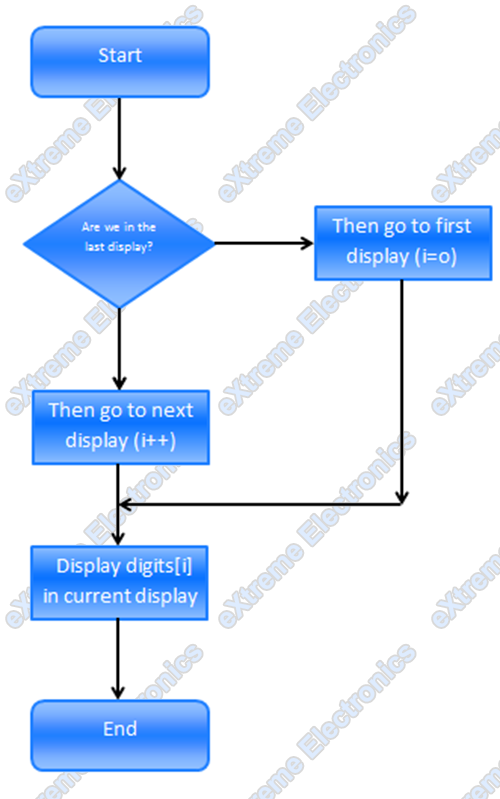
The actual programming will be covered in next tutorial. In this part we will simply see the steps involved.
We will use the TIMER0 to refresh our displays. To learn about timer please see the previous tutorial. The timer will interrupt the CPU at predefined time interval an the CPU will switch to next display and display a digit there.
An array variable
uint8_t digits[3];
will hold the digits for the three displays what ever we need to display on the displays we store them there. So to display “911” on the display we store.
digits[0]=1;
digits[1]=1;
digits[2]=9;
The ISR of TIMER0 Overflow is as follows
We set the TIMER0 prescaler as 256 so the sytem clock i.e. 16MHz is divided by 256 and the timer increment its value at 16000000/256 = 62500Hz i.e. 62.5KHz And timer overflows when its value changes from 255 to 0 so the frequency of Overflow is 62.5 KHz/ 256 = 244.140625 Hz As we switch display in each ISR the display of switching is 244.14 Hz since 3 switching are needed to completely draw a three digit number so the frequency of display update is 244.14/3= 81.38 Hz So we draw the complete digits approximately 81 times per second !!! This is too fast for our eyes to catch up so we see all three digits lit simultaneously. So friends this was the theory behind one of the most used techniques in MCU design world. You must have seen these Seven Segments used in weighing machines,PCOs and even currency counters in banks they all use this technique of Multiplexing the displays. Many microcontroller projects published in net of magazines uses multiplexed seven segment displays and this article will help you understand them. I said it all, now its your turn so all of you get ready for some typing because I need your comment on this post, simply say anything you think good or bad. While I write the next tutorial I will be heartily waiting for your comments.
|
WhatsNext ? |
We will write the code for this in AVR-GCC. Proceed to next part. Related
|
Facing problem with your embedded, electronics or robotics project? We are here to help!
Post a help request.
Avinash
Avinash Gupta is solely focused on free and high quality tutorial to make learning embedded system fun !
Follow Me:


nothing to say.
great job!
thank you very much.
In the display animation, the display names are the same (DISP-1), but I think that the names would be DISP-1, DISP-2 and DISP-3.
By the way, it´s a great job.
Thank you.
Thanks a lot for your work.
Hmm, few topics where not included particulary the effect of multiplexing to its power requirement and frequency response specially when Large 7 segment (5″) are used.
Hmm, few topics where not included particulary the effect of multiplexing to its power requirement and frequency response specially when Large 7 segment (5?) are used as the number of 7 segment increases to 4 and up.
How to multiplexed the common anode 4-inch big seven segment display with microcontrollers? cos they need 12V and if i apply 12V to emitter, it will burn my micro
Use NPN transistor for big seven segment such as TIP31/33/35 or BC337/338 but using PNP transistor to supply 12V to seven segment and that too controlled by MCU may have many problem to appear.
i need to handle with 64 seven segment, is this work? and how about wire connection with atmel 89S52?, thank u.
Well done with your explanations. I have enjoyed your graphic animations in many of your posts. I plan recommend your tutorials to several people I know just starting out in MCUs. Keep up the good work.
Love your tutorial. very easy to understand. its help me a lot. thank you.
Great explaination..:) thank you…But I would ask u How to write program to display data onto 4-digit multiplexed 7-segmentdisplays? in asemmbly not C….?so controlling for digits by PORTD(D0…D3) and controlling segment’s leds by PORTB(B0…B7)..thank U
Thanx i needed this info.
nd, u helped in d nik of time 🙂
all D Best, buddy.
mate you born to teach
what is your occupation?
can i have your mail address?
regards
carlos
@Carlos,
Thanks! But I don’t like teaching.
Great! Tu muy bien!
Pingback: Interfacing Seven Segment Displays | eXtreme Electronics
Pingback: Multiplexed Seven Segment Displays – Part II | eXtreme Electronics
Pingback: Digital Stopwatch | Priyank
Great work! However I have a query. Is system clock 16mhz of 16/4, i.e, 4 mhz.
@elecengr
Why you think the clock is 16/4 ? Any reason ? where did you get that ‘4’?
I thought 16MHz is external crystal frequency. So the frequency of executing each instruction is 16/4 as execution of each instruction takes 4 clock cycles. Isn’t it?
I am a beginner and trying to learn. Please help.
The value ‘4’ probably came from your guess, but it should really come from the ‘datasheet’
Yes you are a beginner but you should avoid picking up those value from your dream (I would suggest datasheet indeed)
In AVR CPU we have 1 instruction per clock (for most instuctions) and the clock input is not divided.
In PIC MCUs the input clock is divided by 4.
So a PIC @ 20MHz CPU clock is 5MHz
while AVR @ 20MHz CPU clock is 20MHz!!!
thanks!
This is what we did, please see the link below: http://www.facebook.com/photo.php?v=355812874448543&set=vb.100000594993920&type=2&theater
@Jerry,
Good!
Pingback: watch using 4 digit 7 segment and avr
too good yaar
better to implement a code.carry on
I like your tutorial..nice and cute to read it..easy to understand..
Really,you are genious !
what you put on your website is very creative and Amazing,i can’t express how much your website helpfull
Here i should say Electronics means Avinash .
Thankyou so much.
You just saved me from the 36 pin usage headache !
Thank you sir Avinash
Sir, your next tutorial’s C code is incomplete. The comments section is also closed so I can’t comment there. I would like to attach the screenshots but don’t know how to do that.