Servo motors are a type of electromechanical actuators that do not rotate continuously like DC/AC or stepper motors, rather they used to position and hold some object. They are used where continuous rotation is not required so they are not used to drive wheels (unless a servo is modified). In contrast they are used where something is needed to move to particular position and then stopped and hold there. Most common use is to position the rudder of aircrafts and boats etc. Servos can be used effectively here because the rudder do not need to move full 360 degrees nor they require continuous rotation like a wheel. The servo can be commanded to rotate to a particular angle (say 30) and then hold the rudder there. Servos also employs a feedback mechanism, so it can sense an error in its positioning and correct it. This is called servomechanism. So if the air flow exerts pressure on rudder and deflects it the servo will apply force in opposite direction and try to correct the error. Say if you ask servo to go and lock itself to 30 degrees and then try to rotate it with your hand, the servo will try hard and its best to overcome the force and keep servo locked in its specified angle.
Servos are also used to control the steering of RC cars, robotics arms and legs.
Their are many types of servos but here we will concentrate on small hobby servos. Hobby servo has motor and its control mechanism built into one unit. They have 3 wire connector. One is for positive supply other for ground and the last one for control signal. The image below shows a common hobby servo from Futaba, its S3003.
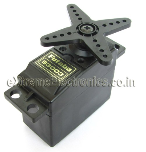 |
Futaba S3003 |
Futaba S3003 wiring.
- RED -> Positive supply 4.8v to 6v
- BLACK -> GND
- WHITE -> Control Signal.
Controlling a Servo Motor.
Controlling a servo is easy by using a microcontroller, no external driver like h-bridge etc are required. Just a control signal is needed to be feed to the servo to position it in any specified angle. The frequency of the control signal is 50hz (i.e. the period is 20ms) and the width of positive pulse controls the angle.
 |
Servo Motor Control Signal. |
For Futaba 3003 servos, I found out the following timings. The relation between the width of pulse and servo angle is given below. Note that these servos are only capable of rotating between 0 and 180 degrees.
- 0.388ms = 0 degree.
- 1.264ms = 90 degrees. (neutral position)
- 2.14ms = 180 degrees.
Controlling Servo Motors with AVR Microcontrollers.
You can use the AVR micro controllers PWM feature to control servo motors. In this way the PWM with automatically generate signals to lock servo and the CPU is free to do other tasks. To understand how you can setup and use PWM you need to have basic understanding of hardware timers and PWM modules in AVR. The following articles may be of great help.
- Introduction to PWM
- Generating PWM Signals by using AVR Timers.
- Introduction to AVR Timers.
- Timers in compare Mode.
Here we will use AVR Timer1 Module which is a 16bit timer and has two PWM channels(A and B). The CPU frequency is 16MHz, this frequency is the maximum frequency that most AVRs are capable of running. And so it is used in most development board like Low Cost AVR Development Board and xBoards. We chose the prescaler as 64. So the timer will get 16MHz/64 = 250khz (4 uS period). We setup Timer Mode as Mode 14.
Timer Mode 14 features
- FAST PWM Mode
- TOP Value = ICR1
So the timer will count from 0 to ICR1(TOP Value). The formula for PWM frequency and calculation for TOP value is given below
So we set up ICR1A=4999, this gives us PWM period of 20ms (50 Hz). Compare Output Mode is set by correctly configuring bits COM1A1,COM1A0 (For PWM Channel A) and COM1B1,COM1B0(For PWM Channel B)
COM1A1 = 1 and COM1A0=0 (for PWM Channel A)
COM1B1 = 1 and COM1B0=0 (for PWM Channel B)
The above settings clears the OC1A (or OC1B) pin on Compare Match and SET ( to high) at BOTTOM. The OC1A and OC1B pins are the PWM out pin in ATmega16/ATmega32 chips. This settings gives us NON inverted PWM output.
Now the duty cycle can be set by setting OCR1A and OCR1B registers. These two register controls the PWM high period. Since the period of timer is 4uS (remember 16Mhz divided by 64?) we can calculate values required for following servo angles.
- Servo Angle 0 degrees require pulse width of 0.388ms(388uS) so value of OCR1A = 388us/4us = 97
- Servo Angle 90 degrees require pulse width of 1.264ms(1264uS) so value of OCR1A = 1264us/4us = 316
- Servo Angle 180 degrees require pulse width of 2.140ms(2140uS) so value of OCR1A = 2140us/4us = 535
If you are using Vigor VS-10 (High Torque Servo) then you need the following values.
- Set OCR1A=180 for 0 degree.
- Set OCR1A=415 for 90 degree.
- Set OCR1A=650 for 180 degree.
In this way you can calculate the value of OCR1A( or OCR1B for second servo) for any angle required. We can see that the value of OCR1x varies from 97 to 535 for servo angle of 0 to 180 degrees.(180 to 650 in case of Vigor VS-10)
Complete AVR ATmega32 Code for Servo Motor Control Demo.
The demo program given below shows how to use servo motors with AVR microcontroller. The job of the program is very simple, it starts by initializing the timer and pwm. Then it locks the servo at 0 degree, then moves it to 90 degree and wait for australian pokies some time, then similarly goes to 135 degree and finally to 180 degrees. The process is repeated as long as powered.
Some Parameter for proper working of program.
- LOW Fuse = 0xFF and HIGH Fuse = 0xC9
- Crystal Frequency = 16MHz.
- Servo Motor is branded Futaba S3003.
- MCU is ATmega32 or ATmega16.
/******************************************************************************

Program to demonstrate the use servo motors with AVR Microcontrollers.

For More Details Visit: http://www.eXtremeElectronics.co.in

Copyright (c) 2008-2010
eXtreme Electronics, India

Servo Motor: Futaba s3003
Servo Control PIN (white): To OC1A PIN
Crystal: 16MHz
LOW Fuse: 0xFF
HIGH Fuse: 0xC9

Compiler:avr-gcc toolchain
Project Manager/IDE: AVR Studio

                                     NOTICE
                           --------
NO PART OF THIS WORK CAN BE COPIED, DISTRIBUTED OR PUBLISHED WITHOUT A
WRITTEN PERMISSION FROM EXTREME ELECTRONICS INDIA. THE LIBRARY, NOR ANY PART
OF IT CAN BE USED IN COMMERCIAL APPLICATIONS. IT IS INTENDED TO BE USED FOR

HOBBY, LEARNING AND EDUCATIONAL PURPOSE ONLY. IF YOU WANT TO USE THEM IN
COMMERCIAL APPLICATION PLEASE WRITE TO THE AUTHOR.


WRITTEN BY:
AVINASH GUPTA
me@avinashgupta.com

*******************************************************************************/
#include <avr/io.h>

#include <util/delay.h>

//Simple Wait Function
void Wait()
{
   uint8_t i;
   for(i=0;i<50;i++)
   {
      _delay_loop_2(0);
      _delay_loop_2(0);
      _delay_loop_2(0);
   }

}

void main()
{
   //Configure TIMER1
   TCCR1A|=(1<<COM1A1)|(1<<COM1B1)|(1<<WGM11);        //NON Inverted PWM
   TCCR1B|=(1<<WGM13)|(1<<WGM12)|(1<<CS11)|(1<<CS10); //PRESCALER=64 MODE 14(FAST PWM)

   ICR1=4999;  //fPWM=50Hz (Period = 20ms Standard).

   DDRD|=(1<<PD4)|(1<<PD5);   //PWM Pins as Out

   while(1)
   {

      OCR1A=97;   //0 degree
      Wait();

      OCR1A=316;  //90 degree
      Wait();

      OCR1A=425;  //135 degree

      Wait();

      OCR1A=535;  //180 degree
      Wait();
   }
}
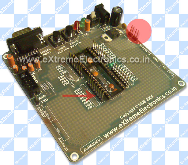
Hardware
You need a basic avr circuit with 5v regulated supply, 16 MHz crystal and proper reset circuit. All these are present in most common development boards.
 |
AVR ATmega32 Controlling a Futaba Servo Motor. |
If you have development boards like Low Cost AVR Development Board or xBoard v2. Then you just need to add the servo motor. Connect RED wire of servo to 5v, BLACK wire to GND and the WHITE wire to OC1A PIN.
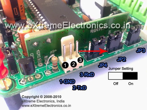 |
The RED Arrow Show the Position of OC1A pin on xBoard v2.0 |
 |
The RED Arrow Show the Position of OC1A pin. |
OC1A PIN is multiplexed with PD5 GPIO pin, that’s why the Low Cost AVR Development Board it is Marked as PD5. The RED Circle in above image is where you can find the 5v and GND supplies. So adding a servo in development board is very easy.
Downloads
- Source Code.
- Complete AVR Studio Project For ATmega16(VS-10 Servo).
- HEX File for ATmega32.
- HEX File for ATmega16 (VS-10 Servo).
- HEX File for ATmega32 (VS-10 Servo).
- Only Servo.c file
- Proteus Simulation for quick testing
NOTE: HEX File can be uploaded to the boards by using a ISP Programmer like the USB AVR Programmer v2.0
Videos
The video demo of above program.
Using VS-10 High Torque Servo
By
Avinash Gupta
www.AvinashGupta.com
me@avinashgupta.com
Facing problem with your embedded, electronics or robotics project? We are here to help!
Post a help request.
Avinash
Avinash Gupta is solely focused on free and high quality tutorial to make learning embedded system fun !
Follow Me:


hey,
it would be gr8 if thr is another tutorial on making a servo to a continuous rotation…………
Hi!
I’d like to say thank you for these tutorials. They are very useful. I started from zero knowledge and now i’ve successfully built a lot of projects based on this website’s tutorial. They are very clear to understand.
If you go out of ideas, i got some: i’d like to control a monitor with avr. I know that the avr’s resources are not high enough for displaying graphics, but i found on the net an example, it displayed characters in some line. An other idea is writing data and reading from memory card. I know it’s a bit advanced, but they could be very useful, if you don’t want to spend money on lcd-s and eeproms.
So thank you again!!!
@Attila,
Thanks! Your Ideas are nice!
They are also in my pipe line will surely do it some day. But the apps like SD Card I/O and VGA/TV out are best done is 16 or 32 bit MCUs. They are also fun to learn!
I am looking to go for Microchip 16 bit PIC MCUs
Hi Avi,
I have brought USB AVR programmer from you about some 2 months back..things are gng fine.
recently i bought a couple of servos from
[link removed]
to test this servos, i have dnloaded and burnt the HEX file on my mega32..
but..the servo didn’t work as it was supposed to do…i am confused
it making it way from 0 to 180 ( * actually. >180 and <200 )and stops right there making some noise..
*when i rotate with hand the servos go more than 180 is this common with servos's
@Feelpawan
May be you should ask them!
a diplomatic answer …though ok..
i am looking for to make an 5DOF robotic arm ..as i said right now i have 2 servos..
can u suggest me..which servos..to use (torque spec)..for holding a light payload..
actually..i want to control R-Arm by my hand movements..
like in this vid http://www.youtube.com/watch?v=9P6Jn0iuYA0
i could’t buy flex sensors as each one costs nearly 1000rs
any alternative to flex sensors..(give me an !dea man)
i think they can be replaced by normal potentiometers..such that when i fold my finger..the pot knob has to move……the same with 4 fingers..possibly thumb also..
movement in X-y-z plane has to be done with accelormeter..
right now am working on it..i would be seeking ur suggestions..along my way (my proj way) 🙂
hie, i am new-bie with no electronic background. i want to ask can i let say move my servo from 0′ to 135′ left, hold it position there for let say 2hrs?? then move back to 0′ position hold there for two hours, then move 135degress right and stay for 2hrs. what s the hardware needed?
i am a farmer to to do automztion. thnk you every one
@Sffian,
The circuit is same just change the delay and the angle requirement !
-Admin
thankyou very much for your reply. so that means i just adjust the setting in the program and i got myself what i want. sorry one more Q, do you think S3003 can pull 4kg of load? i’m trying to build automatic egg turner..
anyway thank you very much..really appreciated it
If you are using the s003 at 6v it will provide a stall torque of 4.1kg/cm which may be adequate for your application . However it also depends on the weight of the egg holding hardware. However its worth a shot. I hope you find my comment helpful !
i actually wanted a program for the same circuit on ASSEMBLY LANGUAGE. it would be really nice of you if you could do that!
Nice explanation of PWM servo control.
Thank You,
GuruSantiago
Want to learn more about electronics?
The GuruSantiago can help. Checkout his videos here:
http://www.youtube.com/user/ElectronicsIsFun
And follow him on twitter @ElectronicsFun
max. how many servos could be controlled using mega32 or mega8.??
mega32 has 4 timers..so only 4 servos could be controlled??
@Anoop,
The method I shouwn in the tutorial controls the servo with zero CPU overhead. If you can give it a slice of CPU time then you can control as many Servo’s as their are i/o pins. This is done by doing PWM using software (thus requires a slice of CPU time)
Avinash.. PLEASE…
1) A How to make your own library tutorial is urgent.
2) Also.. A why and how of eeprom
@William,
How to make Library
http://www.nongnu.org/avr-libc/user-manual/library.html
EEPROM
https://extremeelectronics.co.in/avr-tutorials/easy-24c-i2c-serial-eeprom-interfacing-with-avr-microcontrollers/
Pingback: Interfacing Ultrasonic Rangefinder with AVR MCUs | eXtreme Electronics
hey thx for sharing.it really help me.
i wanna ask you how we find the relation between the width of pulse and servo angle.can we find it?becouse i want to find the characteristic of my servo.can u email me at
boenklon2@yahoo.co.id
thx for the answer then.
hi,
When we search Google for various microcontroller tutorials, links to your tutorials come on the first page itself. Fantastic !!…. shows how popular your tutorials are.
You make it all so easy, otherwise getting started could have been quite difficult for newbies like me. Great Work !
—————————
Re the tut on servos:
Your code above sets values to OCR1A; can we use OCR1B to control another servo with the same configuration of mode, prescaler etc.?
how many servos can we control from a single mic board ( ATMega 32 ) ?
I have heard that timer0 & timer2 can be used but we will lose positional accuracy of the servos. Is there a work around ?
Thanks a lot for your time & effort.
Venks
excellent tutorials. What makes this tutorials unique is the simplicity and the structuring.
Can we control three servo motors at the same time using atmega16 or 32… as in we can control two through the OCR1A and OCR1B pins but is the third motor control possible…??
Hi. Great Tutorial. I am using an ATMEGA8 with 4MHz crystal so need to make changes accordingly. I have made some changes to TCCR1B as follows:
TCCR1B|=(1<<WGM13)|(1<<WGM12)|(1<<CS11); //PRESCALER=8 MODE 14(FAST PWM)
This should give a timer period of 2uS instead of 4uS. I have set ICR1=9999 (for 50HZ) and set DDRB PB1 and PB2 as outputs. In the main function, OCR1A values have been doubled to give the same period and same angles.
It still doesn't sem to work for me. I have no oscilloscope but my multileter measures a 12.5hz output. (Approx) Have I missed something out? Also I didn't understand:
LOW Fuse: 0xFF
HIGH Fuse: 0xC9
Can you please give me some pointers on where I have gone wrong. Thanks
@Todd
Your problem is crystal clear to me. You are getting 12.5Hz output that is exactly 1/4 of the required 50 Hz that is because you have attached a crystal of 4MHz and thought that AVR will auto detect the presence of crystal and use it. But it is not the case AVR are shipped from factory with a setting to use internal 1MHz crystal. So they do not require external crystal to run. In order to use an external crystal (or any other clock source which AVR supports) you need to give explicit intruction to the AVR CPU. Since these type of setting are core setting they must be known to AVR before it can start executing thus cannot be defined in software. They are configured using FUSE bytes of AVR.
That is why I told to set fuse bits as
LOW Fuse: 0xFF
HIGH Fuse: 0xC9
REMEMBER THE THINGS WONT WORK UNLESS YOU DO EXACTLY AS I DESCRIBE.
OR YOU DON’T UNDERSTAND WHAT YOU ARE DOING AND WHAT YOU NEED TO DO
Yes you missed out to program the FUSE bits!!!
Without it the MCU is running exactly 4 times slower than you are expecting it!
In this case at least it is doing something (like generating 12.5 Hz instead of 50 Hz)
It it were some time critical code (Like serial communication) it simply did nothing!
Or in case of you program running faster that expected (if code was for internal 1MHz osc but your MCs Fuse were set to use external crystal)
then most of the program like LCD interface etc would not work. My program already communicates with other peripherals LCD at highest possible speed. If your code run any faster, LCD could not keep up with it and fail!
So try to understand what you are doing and don’t skip steps!
But your comment has important data that can be helped in solving your problem
You told that
1)The frequency counter showed 12.5Hz
2)I didn’t know the fuse bits
The info you gave were enough to solve your problem. So I took time to help you.
Many other peoples just says “It is not working.”
And I simply press “Delete Comment” button! Its simple.
Hi Avinash
Thanks for the insight. It didn’t occur to me that the 12.5Hz signal is exactly 1/4 of the 50Hz that I expect. Now it is indeed very clear. In AVR studio, under configuration, I had already set the clock speed to 4MHz. I guess this only tells the compiler for debug purpose and doesn’t actually setup the AVR. I will find out where to set the fuse bits. Since I use Ponyprog and a home made board to program my AVR, I shall try to identify where those settings can be found in Ponyprog. Thanks again for the help and the brilliant quality of your tutorials.
@Todd,
For Ponyprog fuse bit setting consult this image.

Hello,
I have problem with servo and lcd interfacing.
I don’t know where can be a problem ? I use avr studio 6. and avr prog mk2
and I set crystal freguenci on 4 mhz.
Thanks for your answer. Bob
Hi Avi,
I am working on 6 DOF robot arm project. i am using 6 servos. I am a beginner in AVR Programming.
I am Using,
Microcontroller: ATMEGA16 with 16MHz crystal
Servo: NRS-785
{
Operating speed: 0.17sec/60 degree
0.6 ms for 0 degree Rotation
2.2 ms for 180 degree Rotation
}
Now,
Prob 1: When i flashed MCU with ur Program. Servo working it is rotating 0 to 180 bt after reaching 180 it is resisting its position at 180.
Prob 2: because i want to control 6 servos, is this possible to control 6 servos using one atmega16 MCU?
Please help me.
@Karan,
Did you bought the Servos or the MCU or the programmer from us ? If NOT their is no point in me helping you. Why don’t you ask the guys whom you paid?
Sorry but I need to pay bills to keep this site running! So I can help only those who can help me.
Good bye.
@ Parkin Furia : you can inf act control 4 servo motors using atmega 32. The other two pins are OCR0 and OCR2.
hi
i m wrking on a project for which i would like to know surely before purchasing if i could run 3 servo motors with this and also if the torque of each being around 10 kgcm.
@db : you can run upto four servo motors, i have tried four for my project. how is torque related here?
@db ravindra is right. Torque isn’t related to programming. It depends on the make of servo. Since servos provide digital control the signal line carries only very small current so any type of servos can be driven by this code+circuit. Only the power supply to the servo needs to be strong.
This is the basic code which teaches you how to control a servo. You need to use the idea tough in this tutorial and expand it to support more servos.
Its like I taught how to catch a fish so that you can catch them your whole life.
Hi Avinash.
I am wanting to build a robo which uses 14 servos.Could you please tell me the development board,servos,and microcontrollers best suitable for my robo.And also the source from where i can buy these components.Please help.I am new to this field.
Hi Avinash bhaiya.
Jst a silly question i hv in my mind, why cant we use _delay_ms() function for the waiting time??
i want to run 8 servo motors using any of the port of atmega16
HI, Great sharing! But i used Attiny2313 microcontroller and control Parallax Standard Servo Motor. Could you advices me how do i modify so only can move the servo motor like yours in 0, 90, 180 degree. your help is much appreciate! Hope to hear from your soon. Thanks.
Pingback: Servo motor VS-2 control
estoy muy interezado en aprender a programar los microcontroladores
Hi avinash! i recently bought a xboard and Servo motor from you online shop. made it run using the tutorial. everything is fine. Now i’m in a plan to make a PID controller implementation for the servo. Is it possible to use the same Motor (modified in some way)?? please give me an insight into this. thanking you.
Hi Avinash,
I am a newbie. How did you come up with the prescalar of 64, which is very important in determining the timing. what is N the prescalar. Is it specific to the servo or board?
Avinash,
Good tutorial, simple and easy to follow.
@Mike
Thanks!
Pingback: [SOLVED] how to control 2 servo motors by atmega32 simultaneously
hi avinash…
thanks for your tutorial. but i am not understanding how to set the fuse bits.is it set by haredairecally or it can set in program??? i am using avrstudio4. i will be great full if you help ma…
how we can use it for preparing a robo which ca move in any direction and can fix the voltage of external meter to a specific voltage!!!!!
why we dont use timer0?
how to make a servo motor controller for auto voltage regulator.
Sorif,here we can not describe it in detail ,so you please post your comment on Forum.
Thank you.
http://forum.extremeelectronics.co.in/
How to control 3 motor servo?
Hello Agung, for controlling three servo motor,as we assume you want to use ATmega32 AVR.Because you posted your comment
on article “Servo Motor Control by Using AVR ATmega32 Microcontroller”.So you can use ATmega32, it has 40 pin.Servo motor
is controlled by PWM, for this purpose 4 PWM channels are available here,called OC0,OC2,OC1B,OC1A. With this you can
control three servo motor.Thank you.
To
Mr. Avinash,
Do you kindly tell me from whic site “proteus AVR simulator” can be freely downloaded.
regards
Hello
at the very outset, thanks a lot for the tutorials, they are very lucid and rich in content.
I am working on final year project , rf controlled surveillance helicopter.
right now, I am confused about which microcontroller to use.
I need help with suggestions on the mcu.
pertinently, I have to control 2 servos in addition to speed control of two motors. Are electronic speed controllers available on your store?
I would need all the requisite hardware. thanks in advance
Hello,
I have problem with servo and lcd interfacing.
I don’t know where can be a problem, I use avr studio 6. and avr prog mk2
and I set crystal freguenci on 4 mhz.
Thanks for your answer. Bob
great tutorial !!
can you tell me how to control 18 servos using AVR microcontroller. is any other external servo controller have to used for this.
Dear Avinash,
Nice to read you again, when I really want to read basics of servo controlling.
It is your hobby to teach us, it is our luck to read you.
Keep it up.
I use graphic LCD board satisfactorily ( IR also! With the help of ProGFX)
@Bharat,
Thanks for your feedback.
Hi,where do u find it?i cant see in datasheet of servo.
”
0.388ms = 0 degree.
1.264ms = 90 degrees. (neutral position)
2.14ms = 180 degrees.
”
and why OCR1A=425 135 degrees?
Would u translate for me?
Another great example of how ATMega32 on Raspberry Pi + Gertboard can be controlled:
http://www.linuxcircle.com/?p=640
sir i wanna driv more than two servo and timers is only one please suggest how to drive many servo motor of robotic hand from a single microcontroller
– hi all
i have projec . help me . i wan use avr buid pwm controll ESC , use variable controll speed motor BLDC , i have codrvision and ATMEGA 16
I am using ATmega32U4 using a 16Mhz clock. I tried your code. It is working except for 1 detail. The total period of the pwm signal is 1ms instead of the required 20ms. I also checked the datasheet for the formula and theorotically I should get a 20ms pwm signal however I am getting 1ms.
i have also defined the use of 16Mhz clock in the code ” # define F_CPU 16000000UL”
Please suggest any solution.and opinions.
@Dinesh
What you have done to clock the MCU @ 16MHz? Just connected the XTAL pins to crystal and expect that MCU will clock using it ?
When some guests visits your home and you offer them food, what you do after placing the items on table?
Obviously you ask “Please have some tea sir”
isn’t it?
In the same way after connecting the crystal you have to ask the MCU, “Please baby, get your clock from this, not from your internal RC!”
Hey, I changed the CLKSEL0 and CLKSEL1 values to set the mcu frequency to 16Mhz low power crystal oscillator(fast rise time mode) and also checked the CLKSTA value to ensure that the crystal oscillator is running and the rc internal osc. is stopped. However I am getting the same result and the total duration I am getting is about 1.6ms instead of the 20ms duration. I am unable to find the possible reason for it. Help would be greatly appreciated.
Do I need to change the fuse bits for that? And if so how do change them? And using what do I load them into the MCU??? For burning the program I am using FLIP 3.4.7 by ATMEL.
why cant we just use the following algorithm
for(i=0;i<50;i++)
{
portb.0=1;
delay_ms(2);
portb.0=0;
delay_ms(18);
}
to rotate it 90 degree
jjike,
Because that code can do nothing more that controlling the servo. That means it takes 100% of CPU time.
If we off load this task to timer that the CPU is 100% free.
It can then read a sensor (or 100 sensors) too at the same time !
It can also update the LCD or other user interface. Like reading the push buttons. Or receiving data over RF.
I don’t NOT teach text book style things !
I prefer practical codes! Those who are brought up in side academic ecosystem can create things that can only run inside the lab NOT on roads.
For that requires guys like Henry Ford or Bill Gates or Thomas Edition those didn’t saw the face of collage teachers ever!
Hey,
I am using microcontroller atmega32u4 to control a vigor VS-11 servo motor. I am working on 2Mhz system clock and providing a pwm of 800usec (0.8ms) to 22200usec (2.2ms) for the angle range of 0 to 180 degree of rotation. However despite the correct PWM signals(verified by a DSO) I am getting the rotation of only 120 degrees. I am unable to understand what could be the possible reason behind this as the PWM signal is correct. I tried the servo on a friends arduino board and it is working perfectly on it.
I also tried direct connection of control signal and also using optocoupler circuit. I am using a power supply of 0-30V with current capacity 0-2A to drive the servo at no load condition.
Please provide any suggestion and solution to this problem.
Hey this tutorial is very helpful.I have to control three stepper motors with a single PWM.I need your help.
does it work for TG9e servo? is the code same or do i need to modify? if yes,then where(in the program)?
can this servo motor be rotated in both direction… i mean say 1st in antclock wise and as it completes its rotation then rotate in clockwise so that the hand once rotated comes back to its original position??? if yes,can i expect a help from u??? thank u…
hello avinash
I was doing the same project . I was using atmega 16 with 2 mhz crystal. The problem is coming that whatever i gave the value to OCR1A the servo motor rotate 180 degree. firstly I thought that my code is wrong but this same thing happen when i used your code given in website.
i used the prescalar 8 so that gives me 250KHZ.
i have generated FAST PWM.
ICR1=4999 for 50 hz.
Plus I cannot get the point of low fuse and high fuse.
Thank you for your good tutorial
Hi
This tutorial is helping me a lot in my project.
Will this code work for all servo. What all change should I make for other servos. Please help.
Sir,
I have bought a TOWER PRO SG90 Servo motor.
I am using timer 0 in Atmega 16 PWM mode (phase correct mode)
I generated a pulse of Ton=2ms,Toff=20ms but the result is nill.
Please tell me how to rotate it.
Hi
I have TowerPro SG 90 Micro Servo Motor and I am using Atmega 16.
Can you please tell me How to rotate it using PWM timer 0,if possible provide me source code
Would you like to tell me component that used on the scheme. The picture not too clear. Please help, thanks
@Hen,
Please click on the schematic to download it in high clarity
Hello,i am looking for code for servo motor using atmega328.Also can i use atmega 32,atmega16 codes for atmega328?
how many servos we can be able to interphase with a atmega32
Hey there, Can you plz explain to me the frequency of servo? I mean is it predefined or we have to set it, if yes then how to find correct working frequency and yes one more thing out of curiosity! Can we control the speed of servo anyhow? Reply will be of great Help. Thanks !
Again excellent post Avinash. Love to follow.
@Matija,
Welcome
hello avinash I am working n a project of balancing a ball on a beam(a very popular one).Please suggest me which motor shall I use a geared dc motor or a serv motor.
thank you
hi! it was great
may i ask you something? how to program servo mg995 motor with avr atmega8535?
please help me, thank you so much! god bless you
@Dhanu,
What you understood after reading the above post?
Hello sir,
Is frequency of control signal is always 50hz or it differs from one servo motor to another?
@Chiranjibi,
It differs from model to model. See specification.
Sir i have atmega32 board with external crsytal oscillator connected to it..now when i am using pwm should i take value of internal clock that is 16mhz or oscillator frequency for finding top value ICR1?
sir i used mg996r servo motor by connecting to pwm port of mcu,5v and ground but it heated up excessively, any solution to this although motor rating is 4.8v-6v.
Servo Angle 0 degrees require pulse width of 0.388ms(388uS) so value of OCR1A = 388us/4us = 97
how do you get the value 0.388ms
can you get more explanation for this example please
i have servo motor and a controller with 8MHZ to generate 50HZ using timer1 make motor rotate 0 , 90 ,180 degrees can you tell me the OCR1A here
I am using two servo to change rotation of ultrasonic sensors and write the one servo motor was rotating but other servo motor was not rotating proper path, I don’t know the problem I wish to controll the 2 servo motors the cover 360° any body provide the code for operating 2 servo motors http://bigbelectronics.in/product.php?product=sg90-9g-mini-servo-9-gram-servo-rc-robotics
can you please share the code for servo motor running with atmega3208 microcontroller
Pingback: Generating servo signal in atmega2560 – GrindSkills