In this tutorial I you show you how to make a very useful expansion board for our PIC development board. It will be a Do It Your self (DIY) LCD Expansion board. The expansion board can be plugged into the PIC development board to add 16×2 Alphanumeric LCD Support to it. Since LCDs are required in many projects and experiments it will be a very helpful board.
I recommend you to read the LCD Interfacing Tutorial before you proceed. It will give you an Idea how LCD is connected to PIC Microcontrollers. So lets start!
Schematic for LCD Expansion Board.
 |
Fig.: LCD Module Interface with PIC Microcontroller. |
The board is very easy to make as the MCU core unit is already done for you. So you need to just care about the LCD part. It consists of the 16×2 LCD Module and A variable resistor (10K) only! Optionally you can add a 47ohm series resistor with the LED backlight of the LCD Module, to enable the backlight. The variable resistor is used to adjust the contrast of the module. If NO text is displayed adjust this pot.
All I/O ports and power supply is available at the top of expansion board.
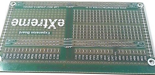 |
Fig.: A blank expansion. |
As you can see the top row in the board lists all I/O port of PIC MCU like, RB7, RA1 etc. For Example, RB7 stands for Port B 7th bit. The row also has regulated 5v supply and GND outputs. So we start by soldering a 40 PIN Right Angled Burg Housing on the Expansion Board. This will help connect it with the PIC development board .
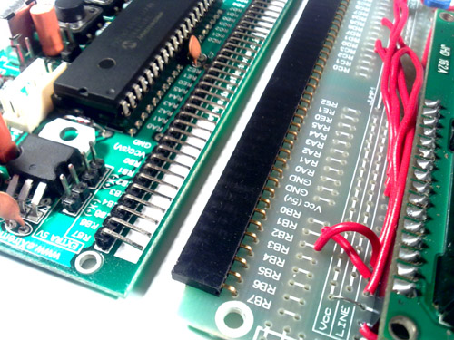 |
Fig.: Connecting Expansion Board with PIC Development Board. |
On the expansion board we solder a 16 PIN Burg Housing, this will help attach a LCD Module. Burg Housing is available in 40 PINs, you have to safely cut it using a small hacksaw blade or a sharp hot knife.
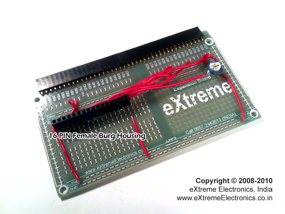 |
Fig.: 16 PIN Burg Housing On the Expansion Board. |
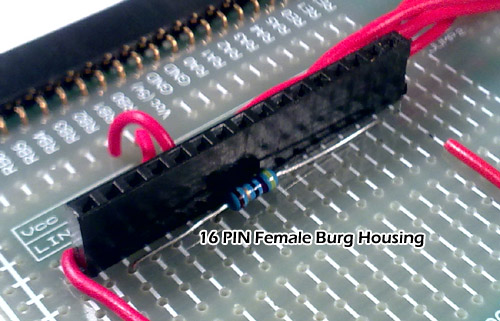 |
Fig.: 16 PIN Burg Housing On the Expansion Board. |
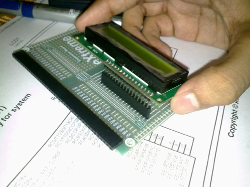 |
Fig.: Mounting the LCD. |
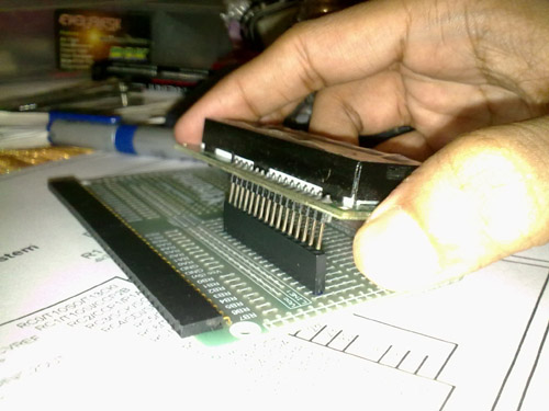 |
Fig.: Mounting the LCD. |
To mount the LCD you need to first solder a 16 PIN Male Burg strip on it. You can break a 40 PIN Male Burg Strip to obtain it.
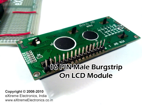 |
Fig.: Headers Soldered on LCD Module. |
After that connect each PIN of the LCD with the PIC I/O Ports as shown in the schematic given above. The LCD PIN number and name are printed on the module it self.
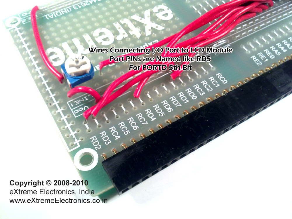 |
Fig.: Connect I/Os to LCD Module. |
Finally connect power PINs and the 10K Preset (the blue thing shown above). Now you can join the LCD Expansion Board to the PIC development board.
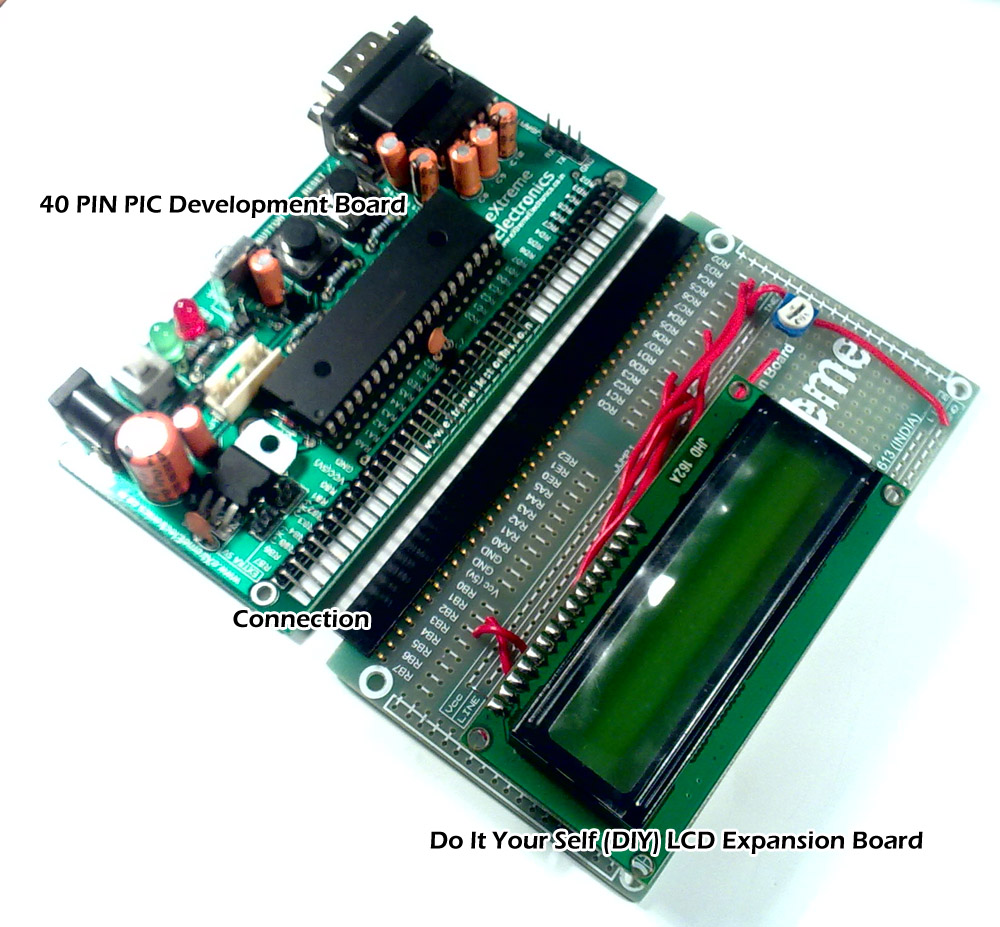 |
Fig.: Together! |
The hardware part is now ready. To learn how to program and use the LCD Modules please read this detailed tutorial.
In all coming tutorials and project we will use the above hardware and software where ever required. So their knowledge will help you understand the code.
In the same way we created the LCD Expansion board you can create any other expansion module to hook in your PIC Development board and extend its capabilities. You can remove one expansion board and hook up another to change it to a completely new project in NO time. You can store a number of project separate on different expansion boards. The CPU core unit is always reused so you don’t have to invest in it each time.
By
Avinash Gupta
May 24, 2010
Facing problem with your embedded, electronics or robotics project? We are here to help!
Post a help request.
Avinash
Avinash Gupta is solely focused on free and high quality tutorial to make learning embedded system fun !
Follow Me:


Pingback: PIC Development Board – Expansion of Board | eXtreme Electronics
Pingback: Using Analog to Digital Converter – PIC Microcontroller Tutorial | eXtreme Electronics
Pingback: Interfacing LM35 Temperature Sensor with PIC Microcontroller. | eXtreme Electronics
Pingback: LCD (16x2) interfacing with dsPIC30F3014
hi sir… am a beginner with pic… i installed mplab ide.. i am actually asked to to lcd interfacing with pic 18 series…buti dono how to start and dont ve code also… i am asd to give the hardware too…. sir please help me… please
@Saranya, how can I help?
i m totally blank… but i can follow ur instructions and execute t… am ready to but stuffs also…
Dear Sir,
Please tell me how to interface acceleromter sensor and Ultrasonic sensor with PIC 18F4550 can You sen d me any sample code .I have Knowledge of PIC 16F877A ,Otherwise tell Difference between PIC 18F4550 and PIC16F877A Code.
Dear Avinash
Hope you will be well , I need help in Fuel dispenser seven segment LCD display control software routines. 8-8-6 or 7-7-5 lcd display . pls help me in this regard.
regards
Irshad baig