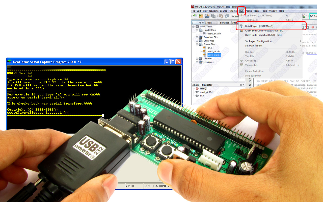
In the last two tutorial we discussed how to make the hardware for serial communication and how to setup a MPLABX Project with support for serial communication functions. Then we complied a demo program to use those serial communication functions and burnt the final hex file to our PIC16F877A development board. Now its time for us to run this demo.
To interact with this demo running on your PIC development board. You need a terminal program. A terminal program is a utility tool running on PC that helps you view text data coming from the serial port and also send data to the port. This is handy for initial development of connected hardwares.
We use Real Term for this purpose.
You can download it from here.
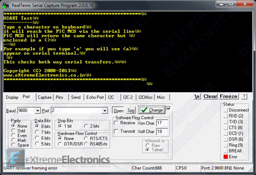 |
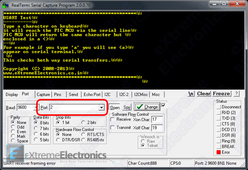
RealTerm |
The top black area show the character data as they are received by the serial port. The received characters are shown in YELLOW coloured text.
The bottom area has lots of tab on it.
The Port tab (shown above) is used to configure the serial port. Configure the port exactly as show in the image above.
- Baud = 9600
- Port = <the serial port number where you have connect the PIC development board>
- Parity = None
- Data Bits = 8 bits
- Stop Bits = 1 bit
- Hardware Flow Control = None
- Make sure "Open" button is NOT pressed !
After RealTerm has been started and configured correctly connect the USB to RS232 Converter on your PC’s USB Port
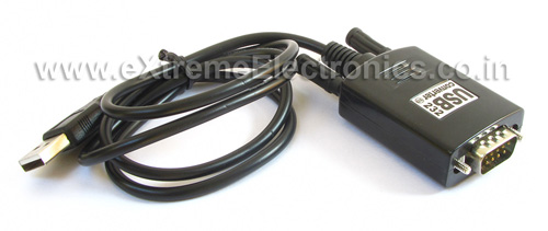 |
Fig. USB to Serial Converter |
Then connect the DB9 Male Part of it (the other end) to your PIC Development Board and Click the Open button on RealTerm.
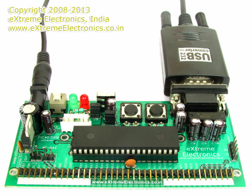 |
Fig. Serial Port Connected |
Power up the development board using a 12V 1A Adapter.
You will received a message on RealTerm as shown in the image below. This message is sent by the PIC over the serial port.
|
Data shown on Terminal Window |
Once you receive this message, you can be sure that data is easily flowing from the PIC microcontroller to the PC. But now we also need to check if the data is able to reach the MCU from the PC or not.
For this, click on the top large black area of RealTerm and then press any key on the keyboard of your PC. RealTerm will send those data to MCU and if MCU is able to read those data, it will reply back with the same character but enclosed in a <>. That means if you press ‘a‘ on keyboard you will see <a> on the terminal window.
This confirms that MCU is also able to read data from the serial port.
Finding the COM Port Number
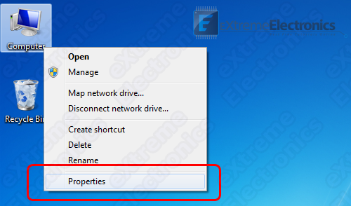
On windows desktop right click on Computer Icon
 |
Windows Desktop |
Select Properties from the context menu.
 |
Select Properties |
This will open up system properties.
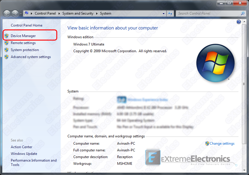 |
System Properties |
From the left hand side, select Device Manager as shown in the image above. It will open up the Device Manager
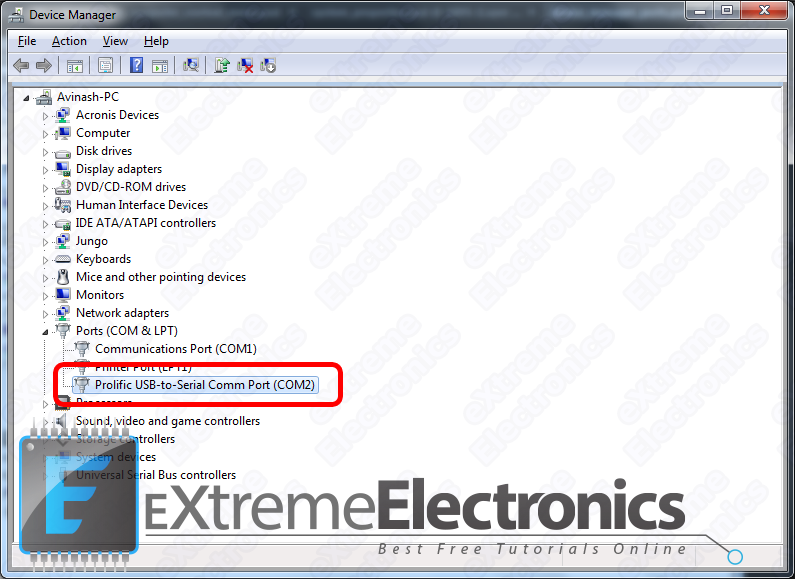 |
Device Manager |
Expand the Ports (COM & LPT) node as shown in the image above. Find the Port Named Prolific USB-to-Serial Comm Port and note the number shown next to it in brackets.
In our case it is COM2 that’s why we have opened Port 2 in RealTerm
 |
Open Port 2 in Real Term |
Important Note !
In order to use the USB to Serial Adapter, it’s driver must be installed correctly ! You can download the drivers from here.
By Avinash Gupta
www.avinashgupta.com
Facing problem with your embedded, electronics or robotics project? We are here to help!
Post a help request.
Avinash
Avinash Gupta is solely focused on free and high quality tutorial to make learning embedded system fun !
Follow Me:


Pingback: USART Library for PIC – Setup on MPLAB X IDE |eXtreme Electronics
hi , I have used your library with PIC 18F4620 and crystal(4 Mhz) , and I have changed the SPBRG=25 @ 9600 baud rate , BRGH=1; BRG16=0.
put it results in writing strange characters on the screen rather than the desired.
Also I have changed the _XTAL_FREQ =4000000 macro
and the configuration #pragma config OSC = XT
to fit my hardware.
I have checked the configurations on the terminal
baud 9600, no parity , one stop bit , flow control=none.
Before I was building my own library but I faced the same problem.
I would be grateful if you helped me to solve the problem and thanks alot for the tutorials.
@Amr Elsayed,
I can help port the lib to your configuration, but that takes time, so I cannot do it for free. If you can pay my fees then we can proceed.
Thanks a lot , for your quick reply ,I have solved the problem ,I was a bit confused about the oscillator configurations , it seems to be complicated to me in PIC uC.
After reading about it in the datasheet ,I have tried the internal oscillator(4MHz) and it’s now working probably.
thanks a lot Mr,Avinash ,and I hope we can deal with each other in the near future.
Hi
how can i read data from excel spreadsheet using you uart code for pic16F877a
thank you
Hello Avinash,
its always a pleasure to read your articles which are very helpful to new comers. I am working on 433MHz RF with PIC16f877A as receiver.I am receiving data from other node and displaying it on lcd. However when I am checking my tx and rx node using hyper terminal they are working fine but as soon as I am communicating the two the receiver receives the data just once/twice and get hangs. I am using 2400 baud rate for both tx and rx node.
It would be very kind if you help me out in the issue.
Thank you
Hello sir,
I’m receiving “UART Receiver Framing error” and some characters are working fine but some are not….my right hand keys are working fine but left hand keys are shows different characters…if i press a key then y is displaying in terminal how can i solve this problem?
I’m using pic18f4550 and using external 20Mhz crystal and my project settings are below:
PLL Prescaler Selection:
Divide by 5(20MHz oscillator input)
System Clock Postscaler Selection:
[Primary Oscillator Src: /1][96 MHz PLL Src: /2]
USB Clock Selection (used in full-Speed USB mode onl…
USB clock source comes from the 96 MHz PLL divided by 2
Oscillator Selection
HS oscillator, PLL enabled (HSPLL)?
Thanks