Tag Archives: AVR

Easy 24C I2C Serial EEPROM Interfacing with AVR Microcontrollers

In this turorial we will see how we can easily interface a 24C series serial EEPROM with AVR microcontrollers. What is an EEPROM? An EEPROM is kinds of novalatile memory, that means it is used for storing digital data permanently without any power suply. EEPROM stands for Electrically Erasable Programmable Read Only Memory. The advantage of these kind of ROMs is that they can be erased Electrically to make them ready for storing new data. Compare this with a CD R disks they can be recorded only once. A small amount of EEPROM is also available internally on the AVR chips. So if the volume of data you want to store is small (say few user names and password) then you can use it. The internal eeprom makes design small and simple. But if the amount of data you want to store is large, say in order of few tens of kilobytes then you have to interface a External EEPROM chip with your AVR MCU. You can store pictures, sound and long texts in these eeproms. Their are many kinds of EEPROM chip available from many manufactures. One very common family is 24C series serial EEPROMs. They are available upto 128KB in size. They uses I2C interface with host controller (MCU) which is a very popular serial communication standard. I […]

PWM Signal Generation by Using AVR Timers.

In the last tutorial you saw how the PWM technique helps us generate analog signals from a microcontroller. In this tutorial we will see how PWM generation is implemented with microcontrollers. Before you begin please see Introduction to PWM Introduction to AVR Timers Generation of PWM signals is such a common need that all modern microcontrollers like AVR has dedicated hardware for that. The dedicated hardware eliminates the load of generation of PWM signal from software (thus frees the CPU ). Its like asking the hardware to generate a PWM signal of a specific duty cycle and the task of CPU is over. The PWM hardware with start delivering the required signal from one of its PINs while the CPU can continue with other tasks. In AVR microcontrolers PWM signals are generated by the TIMER units. (See AVR Timer Tutorials) . In this tutorial I will give you the basic idea of how PWM signals are generated by AVR timers. Their are two methods by which you can generate PWM from AVR TIMER0 (for ATmega16 and ATmega32 MCUs). Fast PWM Phase Correct PWM Don’t worry from their names they will become clear to you as we go on. First we will be considering the Fast PWM mode. PWM Generation Fundas We will use the simplest timer, TIMER0 for PWM generation.(Note […]

Introduction to PWM – Pulse Width Modulation.

A digital device like a microcontroller can easily work with inputs and outputs that has only two state, on and off. So you can easily use it to control a LED’s state i.e. on or off. In the same way you can use it to control any electrical device on/off by using proper drivers (transistor,triac, relays etc). But sometimes you need more than just "on" & "off " control over the device. Like if you wanna control the brightness of a LED (or any lamp) or the speed of DC motor then digital (on/off) signals simply can’t do it. This situation is very smartly handled by a technique called PWM or Pulse Width Modulation. PWM is the technique used to generate analogue signals from a digital device like a MCU. Almost all modern MCUs have dedicated hardware for PWM signal generation. In this tutorial we will learn the basics of PWM technique and later on we will see how to implement PWM generation with AVR microcontrollers. PWM : Pulse Width Modulation A digital device, like a microcontroller can only generate two levels on its output lines, HIGH=5v and LOW=0V. But what if we want to generate 2.5v or 3.1v or any voltage between 0-5 volt output ? For these kinds of requirement, instead of generating a constant DC voltage output […]

Using the USART of AVR Microcontrollers : Reading and Writing Data

Till now we have seen the basics of RS232 communication, the function of level converter and the internal USART of AVR micro. After understanding the USART of AVR we have also written a easy to use function to initialize the USART. That was the first step to use RS232. Now we will see how we can actually send/receive data via rs232. As this tutorial is intended for those who are never used USART we will keep the things simple so as to just concentrate on the "USART" part. Of course after you are comfortable with usart you can make it more usable my using interrupt driven mechanism rather than "polling" the usart. So lets get started! In this section we will make two functions :- USARTReadChar() : To read the data (char) from the USART buffer. USARTWriteChar(): To write a given data (char) to the USART. This two functions will demonstrate the use of USART in the most basic and simplest way. After that you can easily write functions that can write strings to USART. Reading From The USART : USARTReadChar() Function. This function will help you read data from the USART. For example if you use your PC to send data to your micro the data is automatically received by the USART of AVR and put in a buffer […]

Using the USART of AVR Microcontrollers.

Welcome to the third part of my RS232 serial communication tutorial. Till now we saw the basics of RS232 communication and made our level converter. Now its time to understand the USART of AVR microcontroller and write the code to initialize the USART and use it to send and receive data. Like many microcontrollers AVR also has a dedicated hardware for serial communication this part is called the USART – Universal Synchronous Asynchronous Receiver Transmitter. This special hardware make your life as programmer easier. You just have to supply the data you need to transmit and it will do the rest. As you saw serial communication occurs at standard speeds of 9600,19200 bps etc and this speeds are slow compared to the AVR CPUs speed. The advantage of hardware USART is that you just need to write the data to one of the registers of USART and your done, you are free to do other things while USART is transmitting the byte. Also the USART automatically senses the start of transmission of RX line and then inputs the whole byte and when it has the byte it informs you(CPU) to read that data from one of its registers. The USART of AVR is very versatile and can be setup for various different mode as required by your application. In this […]

Using IR remote with AVR MCUs

Hi Friends, Welcome to my AVR tutorial Series. In this article I will describe my Infrared Remote Control Library. Hope you will enjoy it. I was very much amazed my remote controls since long. The simple circuits described in magazine were just operated like a switch and can only switch on and off an application. That means only single channel. That was of not much use. What I wanted was access to each key on remote control. I wished I could decode the signals generated by common remotes controls found in our homes. This way I could make multi channel remote controls for any project. So I went on and after some web research, coding and debugging I finally succeeded ! Actually I completed that more than one and half year ago (in may 2007). And now I thought I should also make it available to others who are in need of it so that they can use it in their projects. So I went on to make it more "clean" and also to make it more "easily portable" so that it can be used with different devices operating at different frequency. And now the result is here, a very easy to use library that can add remote control feature in any of your AVR project ! Using a IR […]

xBoard™ :: ATmega32 Development Board.

Here are some Videos that demonstrate the xBoard – a easy to use but powerful development system for Atmel AVR ATmega32 microcontrollers. For complete information about the xBoard™ see http://xBoard.eXtremeElectronics.co.in Video #1 xBoard™ :: AVR Dev-Board – Introduction This video tutorial gives you a quick introduction of the xBoard; easy-to-use and powerful Atmel AVR AtMega32 Microcontroller Development Board. Video #2 xBoard™ :: AVR Dev-Board – Hello World In this tutorial we will introduce you to the basic steps needed set-up and develop programs for the xBoard. We’ll write a LED blinking project which is a Hello World project for microcontroller arena. xBoard – a easy-to-use and powerful Atmel AVR AtMega32 Microcontroller Development Board. Video #3 xBoard™ :: AVR Dev-Board – LCD Interfacing This video tutorial teaches you how you can interface a standard 16×2 LCD Module with the xBoard – easy-to-use and powerful Atmel AVR AtMega32 Microcontroller Development Board. Video #4 xBoard™ :: AVR Dev-Board – IR-Remote This video tutorial shows you how to interface a DVD Player Infrared Remote Control with the xBoard, a easy-to-use and powerful Atmel AVR AtMega32 Microcontroller Development Board.

Interfacing Temperature Sensor – LM35

By interfacing different types of sensors with our MCU we can sense the environment and take decisions, in this way we can create "smart" applications. There are wide variety of sensors available. In this tutorial we will learn about a popular sensor LM35 which is precision centigrade temperature sensor. It can be used to measure temperature with accuracy of 0.5 degree centigrade. We can interface it easily with AVR MCUs and can create thermometers, temperature controller, fire alarms etc. Things Required   S. No. Item Image 1 28 PIN AVR Dev Board Contains the core AVR circuit including 5v regulator, reset, ISP. 2 Seven Segment Display Module Four common anode displays multiplexed with driver transistors and current limiting resistors. 3 Single Pin Female to Female Burg Wires Used to interconnect the two boards. And the sensor.   4 USB AVR Programmer To upload the program to the development board. 5 LM35 Temperature Sensor   LM35 LM35 by National Semiconductor is a popular and low cost temperature sensor. It is also easily available. You can buy one from here online. It has three pins as follows. Fig – LM35 Pin Configuration     The Vcc can be from 4V to 20V as specified by the datasheet. To use the sensor simply connect the Vcc to 5V ,GND to Ground and the […]

ADC (Analog To Digital Converter) of AVR Microcontroller

Most of the physical quantities around us are continuous. By continuous we mean that the quantity can take any value between two extreme. For example the atmospheric temperature can take any value (within certain range). If an electrical quantity is made to vary directly in proportion to this value (temperature etc) then what we have is Analogue signal. Now we have we have brought a physical quantity into electrical domain. The electrical quantity in most case is voltage.To bring this quantity into digital domain we have to convert this into digital form. For this a ADC or analog to digital converter is needed. Most modern MCU including AVRs has an ADC on chip. An ADC converts an input voltage into a number. An ADC has a resolution. A 10 Bit ADC has a range of 0-1023. (2^10=1024) The ADC also has a Reference voltage(ARef). When input voltage is GND the output is 0 and when input voltage is equal to ARef the output is 1023. So the input range is 0-ARef and digital output is 0-1023. Fig: ADC Theory Inbuilt ADC of AVR Now you know the basics of ADC let us see how we can use the inbuilt ADC of AVR MCU. The ADC is multiplexed with PORTA that means the ADC channels are shared with PORTA. The ADC […]

Using Internal peripherals of AVR MCUs.

Each AVR MCU has several internal peripherals that give powerful abilities to your projects. For example internal ADC can be used to convert analog value (say voltage output of some sensor) to a digital value that you can use. And a USART(Universal Synchronous Asynchronous Receiver Transmitter) can be used to connect your MCU with PC. (Example use – A PC serial mouse or A PC controlled Toy Rocket Launcher). This tutorial gives you overview of the process used to interface with these peripherals. Internal peripherals. Now you know the basics of peripherals, lets see what peripherals are available in ATmega16 MCU. Two 8-bit Timer/Counters with Separate Prescalers and Compare Modes One 16-bit Timer/Counter with Separate Prescaler, Compare Mode, and Capture Mode Real Time Counter with Separate Oscillator Four PWM Channels 8-channel, 10-bit ADC 8 Single-ended Channels 7 Differential Channels in TQFP Package Only 2 Differential Channels with Programmable Gain at 1x, 10x, or 200x Byte-oriented Two-wire Serial Interface Programmable Serial USART Master/Slave SPI Serial Interface Programmable Watchdog Timer with Separate On-chip Oscillator On-chip Analog Comparator Interfacing Technique. Fig: Using internal peripherals of AVR MCUs. A peripheral is connected to MCU by some special registers. The different registers of any peripherals can be logically of two types- 1)Data registers – which usually contains some data, say byte received from USART or […]

Using LCD Module with AVRs

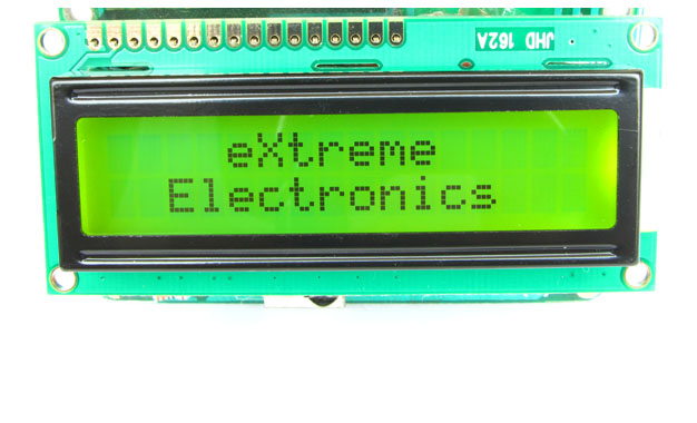
When you start working with LCD modules you will start feeling the real power of MCU and your imaginations will be touching sky you will wonder how many exciting a powerful gadgets you can create and that’s so very easily. LCD Modules can present textual information to user. It’s like a cheap “monitor” that you can hook in all of your gadgets. They come in various types. The most popular one can display 2 lines of 16 characters. These can be easily interfaced to MCU’s, thanks to the API( Functions used to easily access the modules) we provide. LCD interfacing is just fun ! Fig: A 16×2 LCD Module Buy LCD Modules Online In India   PIN Configurations. The lcd modules has 16 PINs for interfacing. The details are given below. LCD Module Pin Configuration 1 VSS (GND Supply) 2 VCC (+5V) 3 VEE (Contrast Adjust) 4 RS 5 R/W 6 E 7 DB0 8 DB1 9 DB2 10 DB3 11 DB4 12 DB5 13 DB6 14 DB7 15 LED + 16 LED –   Connection with ATmega8/ATmega168 etc. The lcd module can be easily connected to the any 28 pin AVR MCU like ATmega8/ATmega168/ATmega328 etc. The diagram below shows the LCD connection with AVR MCUs port pins. Fig: Connection with 28 PIN AVR MCUs Connect the required pins of […]

DC Motor Control using AVR MCUs

Motor gives power to your MCU. Ya power to do physical works, for example move your robot. So it is essential to know how to control a DC motor effectively with a MCU. We can control a DC motor easily with microcontrollers. We can start it, stop it or make it go either in clockwise or anti clock wise direction. We can also control its speed but it will be covered in latter tutorials. A Geared DC Motor. DC Motor A DC motor is electromechanical device that converts electrical energy into mechanical energy that can be used to do many useful works. It can produce mechanical movement like moving the tray of CD/DVD drive in and out (you may like to try it out Go to My Computer, right click the drive icon and click “Eject”). This shows how software controls a motor. DC motors comes in various ratings like 6V and 12V. It has two wires or pins. When connected with power supply the shaft rotates. You can reverse the direction of rotation by reversing the polarity of input. Control with AVR MCUs As the MCUs PORT are not powerful enough to drive DC motors directly so we need some kind of drivers. A very easy and safe is to use popular L293D chips. It is a 16 PIN […]