Tag Archives: clock

DS1307 Based RTC Module

An RTC Module or a Real Time Clock Module helps a system keep track of current time (hour, minutes and seconds). It automatically increments the time without any help from the host (microcontroller). Other benefit is that it has a backup power supply from a small coin cell that help it maintain the time in absence of power. It needs very small power in backup mode so that the coin cell last for years! One such RTC IC is DS1307. It communicates with the host using I2C serial interface. We have put all the required components in one PCB to make a neat module that we can hook up to our MCUs like PIC or AVR. After the experiment you can put the module safely in your drawer, bring it out after an year and still it will give you the correct time! DS1307 Module Schematic DS1307 Based RTC Module Schematic DS1307 Module Fabricated ! DS1307 Based RTC Module   Professional DS1307 RTC module     Connection with MCU The SCL line of RTC Module will be connected to SCL line of MCU similarly the SDA line will be connected to the MCU’s SDA line. The RTC Module should be powered from the microcontroller development board. Most of our boards have extra 5v output points. Please see their documentation for […]

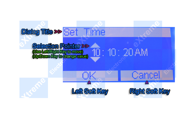
Time Input Dialog for Graphic LCD

GUI Frameworks of all modern OS like Windows, Linux (Qt & GTK+), MAC etc have a concept of standard dialogs. For example all applications running under Windows shows the same file open dialog for selecting a file. Similarly their are standard dialogs for folder selection, colour selection, font selection etc. This concept has several advantages, and the most important is a easy user interface. Since the user is already familiar with file selection in one application, he/she can use file open dialog of any application. Building on the same concept our GUI framework for ProGFX (avr glcd driver) will too have many standard dialogs for common user interface. In this tutorial we will build the "Time Input Dialog" that helps programmer ask the user to input time. The time could be anything like :- "On" or "Off" time for a relay in a timer application. Alarm time in an alarm clock application. Period start time in a school bell application. And many others. The programmer just need to call the function. void ShowGetTimeDlg(uint8_t *h,uint8_t *m,uint8_t *s,uint8_t *am_pm) It takes four parameters hour, minutes, second and am_pm. All parameters are passed by reference(pointer actually), this is because the function modifies the value of those variables. It shows a dialog as shown below :- Time Input Dialog The user can use the […]

AVR Project – Relay Timer with ATmega8 AVR MCU

Timers are widely used in industrial and domestic application for automating tasks. Microcontrollers can be used to design versatile and accurate timers with ease. Here I present a simple timer that can be used to turn on/off a load after user specified time. The Timer uses a standard 16×2 lcd module for user interface (UI). User can set the time using a 3 button keypad. After that Timer is started. While count down is in progress, the time left is displayed on screen. The program use our LCD driver library more details of which can be found in here. Use avr-gcc + AVR Studio to compile. The prototype was developed using xBoard MINI, a low cost easy to use ATmega8 development board. The program was burned to the MCU’s flash memory using eXtreme Burner – AVR Software and Hardware. A basic knowledge of working with different tools of AVR development is required, so please refer to following articles. Note: Fuse Must be set as follows, HIGH FUSE=C9 LOW FUSE=FF (Very Important) If display is blank please adjust RV1 Part List 01 ATmega8-16 PU U1 02 16×2 LCD Module LCD1 03 16 MHz Crystal X1 04 BC548 Transistor Q1 05 1N4007 Diode D1 06 4.7K Resistor R1,R2 07 10K Variable Resistor VR1 08 22pF Disk Capacitor c1,c2 09 0.1uF Disk Capacitor […]

AVR Project – Digital Stop Watch with ATmega8

Hello Friends, In this tutorial we will make a "Digital Stop Watch" using an AVR ATmega8 Microcontroller. This will help you learn many concepts like Multiplexed Seven Segment Display Interfacing Using AVR Timers Using Interrupts And many others too. The code is written in C language for avr-gcc (WinAVR) . Fig.: Digital Stop Watch Prototype Steps to Build the "Digital Stop Watch" using AVR ATmega8 MCU Make the circuit according to the schematic on general purpose PCB or a BreadBoard. Make a project in AVR Studio and add a new file to the project. Copy/paste the "c" code. Set optimization as "o2" and CPU frequency as 16000000Hz. Save and Build the project. You will get a HEX file. Burn this HEX file to an ATmega8 MCU using a tool such as eXtreme Burner AVR. Set High Fuse = C9(Hex) Low Fuse = FF(Hex). How to do this depends on you programmer software. I have use a xBoard MINI development board for fast and easy prototyping. The Displays+Transistors+Key are on the Veroboard while the Core CPU unit + power supply is in the xBoard MINI. It can be programmed "In System" over USB Port using eXtreme Burner – AVR software toolkit. Fig.: Digital Stop Watch made using xBoard MINI   How to Use the "Digital Stop Watch" When initially powered up […]

Timers in Compare Mode – Part I

Hi Friends, In last tutorials we discussed about the basics of TIMERs of AVR. In this tutorial we will go a step further and use the timer in compare mode . In our first tutorial on timer we set the clock of the timer using a prescaler and then let the timer run and whenever it overflowed it informed us. This way we computed time. But this has its limitations we cannot compute time very accurately. To make it more accurate we can use the compare mode of the timer. In compare mode we load a register called Output Compare Register with a value of our choice and the timer will compare the current value of timer with that of Output Compare Register continuously and when they match the following things can be configured to happen. A related Output Compare Pin can be made to go high,low or toggle automatically. This mode is ideal for generating square waves of different frequency. It can be used to generate PWM signals used to implement a DAC digital to analog converter which can be used to control the speed of DC motors. Simply generate an interrupt and call our handler. On a compare match we can configure the timer to reset it self to 0. This is called CTC – Clear Timer on […]