Tag Archives: ir sensor

Line Following Robot using AVR ATmega8

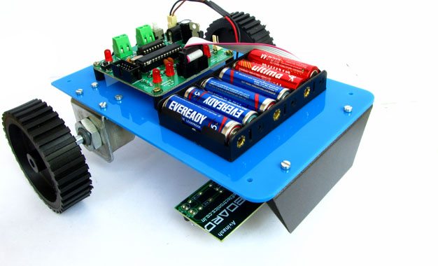
One of the most basic autonomous robot you can build is a line following robot(LFR). This type of robot is run over a white surface which has an arbitrary path drawn over it by using back paint. The task of the robot is to run exactly along this painted path. You may note that the surface may also be black(or any other dark colour), in that case the path is a light colour like white. Please watch the following video for a LFR in action. Designing an LFR At minimum our LFR design require the following components. A sensor to detect the line on the surface.(It can be a simple IR Reflectance Sensor or an high end camera!). We will use a simple IR based sensor, it is cheap and easy to build and use. This article describe how to make a line sensor array. A microprocessor to run the code that takes inputs from the sensor and control the motion of robot. We will use a cheap single chip computer called an microcontroller (MCU). A popular family of microcontroller is AVR series from Atmel. A member of the popular family is ATmega8. ATmega8 is chosen because it has just the required amount of resources and is very low cost. The MCU cannot drive the motors (used to actually make […]

Obstacle Avoiding Robot using AVR ATmega32 – Part III

Hello All, Welcome to the third part of the Obstacle Avoiding Robot Tutorial. Till now we have completed the mechanical construction and made the sensor for our robot. I have shown you how to control the motors and read values from sensor in last two parts of the tutorial. In this tutorial we create the master program for our robot. The job of the program is simple, to read values from the sensors, make a decision and command two motors. In this way our robot will roam about the room avoiding obstacles in its path. In our program we define three constants, namely RTHRES,CTHRES and LTHRES in the following way :- //Threshold Values For Sensor Triggering #define RTHRES 195 #define CTHRES 275 #define LTHRES 195 The constant value next to them is the triggering values. You can get this values as described in previous tutorial. Simply run the IR Sensor Test program and bring any obstacle near the sensor at about 15cm (6 inches) and note down these values against respective sensor threshold values. Do same for all three sensor. Now the program knows when the value comes near this threshold value, the sensor has a obstacle in front of it. Note that the value shown above is may not match with the values you obtained, that OK. In our […]

Obstacle Avoiding Robot using AVR ATmega32 – Part II

Hello and Welcome back to the second part of Obstacle Avoiding Robot Tutorial. In the last part we studied the drive system and the mechanical construction of our robot. In this part we will make the sensor part. The sensors will help our robot detect obstacle in its path. The sensor system is of very basic type of infrared(IR) reflectance sensor. It is made up of an IR Transmitter and an IR receiver. The IR transmitter is an IR LED which emits light in IR spectrum that is invisible to human eye. The IR receiver can detect those rays. A Matching Pair of IR Rx and Tx, The Blue One is Tx (LED). The IR Sensor Element The IR Sensor element is made up of an IR Tx,IR Rx and few resistors. The schematic is given below. We need three such elements mounted in front of the robot to sense obstacles in front of it. IR Reflectance sensor schematic. As you can see the sensor element has two pins for power supply and an Output pin. The output is a variable voltage between 0 and 5v depending on the type and distance of the obstacle. It tends to 5v as some obstacle comes near it. IR Sensor Construction Guidelines. The value of R1 is 150 ohms and R2 is 22K. […]