Tag Archives: lcd

Microwave Controller using ATmega8 – AVR Project

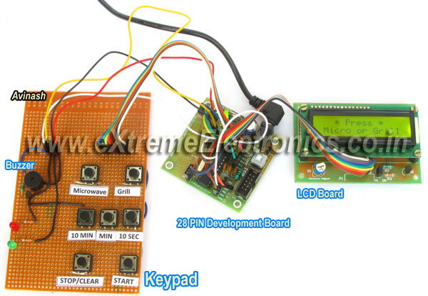
Microwave Controller’s User Interface Fig. Microwave Timer using AVR ATmega8   The user interface has the following parts. Output Device: A 16×2 alphanumeric LCD Module is used as the main output device. It can display numbers, alphabets and few symbols. It can show two line and each line can have 16 characters. The backlight enables the text to be visible even in dark. A buzzer beeps when the system receive input from the user and the input is successfully processed. For example if the user presses 10 MIN button to increment timer by 10 min and this is successfully carried out the buzzer beeps. But if the timer is already at the maximum setting (90 minutes) the operation could be carried out, so the buzzer does not beeps. This buzzer also beeps a few time when the food is ready (countdown is finished) Input Device: Input from user is received by a keypad which has seven push buttons. The details of button is given below. Button Function Microwave Selects Microwave mode. Grill Selects Grill mode. 10 MIN Increment timer by 10 minutes. MIN Increment timer by 1 minute. 10 SEC Increment timer by 1 sec. STOP/Clear If the microwave is in on condition, this button turns it off and pauses the timer count down. If you are setting the timer, […]

Making A Thermometer with PIC16F877A

At basic level on microcontroller you can create this interesting project of digital thermometer. It teaches you how to acquire analog data from a sensor and display it on a lcd. We will use a popular MCU PIC16F877A to implement this mini project. The temperature will be read using a LM35 precision sensor. Final result will be shown on a 16×2 alphanumeric lcd module. Fig. PIC16F877A Based Thermometer with LCD   Stuffs Required S. No. Item Image Cost 1 40 PIN PIC Development Board Rs. 769 2 16×2 LCD Board Rs. 296 3 Single PIN Burg Wires Female/Female 20 units Rs. 100 4 12V 1A DC Adapter Rs. 127 5 LM35 Rs. 60     Total Rs. 1,352 Connections The PIC16F877A development board has the PIC16F877A microcontroller chip and its supporting basic circuitry all in a nice high quality PCB. The development board comes fully assembled and tested, thus makes it ideal for doing experiments for learning by beginners. 40 PIN PIC Development Board In the bottom portion of the pic development board you can see a row of male headers. Most of these pins are the microcontrollers general purpose input/output lines and the rest are 5v and GND supply lines. Using these pins you can connect external peripherals (like the LCD board or something else) to do your experiment. […]

LCD Library for PIC – Setup on MPLAB X IDE

This article describes the setup and use of the C library for hd44780 based alphanumeric lcd modules. This library is also available for the AVR family of microcontrollers. This part is focused on its usage with PIC16F series of MCUs from Microchip. Here we describe how to setup a MPLAB X project with support for lcd related functions. The library is designed for compilation and use with Microchip’s XC8 C Compiler. Fig. LCD Demo   Creating a New Project in MPLAB X You can create a new project using the MPLAB’s Start page as shown below. Fig. MPLAB X Start Page Alternatively you can use File->New Project Fig. Select New Project from File Menu And for those who love the Keyboard over mouse can hit <Ctrl>+<Shift>+<N> Any of the three method will launch the New Project Wizard as shown below. The first step is the selection of project type. From the Categories list select Microchip Embedded and from Projects select Standalone Project. Fig. Project Type Selection Second step is the selection of device for which the project is targeted. Select Mid Range 8-bit MCUs (PIC12/16/MCP) in Family and PIC16F877A in Device. Fig. Device Selection Third step is the selection of debug tool. For that select Simulator. Fig. Tool Selection Microchip MPLAB lets you install more that one compiler. It also […]

LCD Module Interface with PIC16F877A

This article describe the hardware setup required for interfacing HD44780 based alphanumeric LCD modules with a PIC16F877A microcontroller. The software part consisting of the LCD library for PIC, its setup and use with MPLAB X IDE and XC8 compiler are described in a separate article. LCD Library for PIC – Setup on MPLAB X IDE A common controller chip used in many alphanumeric LCD module is the HD44780. The purpose of the controller is to generate pixel patterns and drive individual pixels of the LCD to show characters and symbols. In this method the main microcontroller running your application code does NOT need to generate the pixel patterns, it just need to tell the controller chip which character or symbol to show the rest is done by the controller, i.e. the HD44780. The same controller chip is used in many differently sized alphanumeric LCDs. Thus the connection schematic and driving code is same. Pin Details of LCD Module All HD44780 based LCD modules have 16 pin connecters. The detail about these pins is given below. Interface pins of LCD Module   Pin Number Pin Name Pin Type Connected with PIC16F877A’s pin 1 VSS Power Supply – 2 VCC Power Supply – 3 VEE Contrast Adjust – 4 RS Control Line RD4 5 R/W Control Line RD5 6 E Control Line […]

Remote Temperature Monitoring using GSM – AVR Project

If you want a live demo of this, please register from the link given below. (Only in Pune) REGISTER NOW! This project can also be implemented using a PIC18F4520 microcontroller. Temperature monitoring have wide application in daily life. In modern day keeping an eye on temperature of places such as server rooms, hospital rooms, warehouses and green houses can help solve many problems. But with the use of normal temperature sensors, someone needs to go to the place in order to view the temperature. But with the development of GSM network, one can easily connect the sensor with GSM network, so that you don’t need to be present near the sensor in order to view the temperature. You can just pick up your cell phone and send a request to your sensor by a text message and in no time you will receive the temperature of the remote place ! The advantage is the you don’t need any kind of "special" device at the receiver end. You can use any cell phone to view the remote temperature. This reduces cost as you already have a cell phone. Other benefit is that the range is not limited. You can be at any place in the world (with mobile coverage of course!), to request temperature data from your room. Fig. SMS Based […]

Interfacing TCS3200 Colour Sensor with AVR ATmega32

Detecting colour of an object can be an interesting and useful electronic application. It can be realized using a colour sensor like TCS3200 and a general purpose microcontroller like AVR ATmega32. TCS3200 Colour Light to Frequency Converter Chip Fig. TCS3200 Chip .   TCS3200 chip is designed to detect the colour of light incident on it. It has an array of photodiode (a matrix of 8×8, so a total 64 sensors). These photodiodes are covered with three type of filters. Sixteen sensor have RED filter over them thus can measure only the component of red in the incident light. Like wise other sixteen have GREEN filter and sixteen have BLUE filter. As you should know that any visible colour can be broken into three primary colours. So these three type of filtered sensors helps measure the weightage of each of primary colours in incident light. The rest 16 sensors have clear filter. TCS3200 converts the intensity of incident radiation into frequency. The output waveform is a 50% duty cycle square wave. You can use the timer of a MCU to measure period of pulse and thus get the frequency. The output of TCS3200 is available in single line. So you would ask how we get the intensity of RED,GREEN, BLUE and CLEAR channels? Well it has two inputs S2 and […]

Displaying Custom Characters on Alphanumeric LCDs

You can use this LCD Custom Char Builder Software to quickly and easily build custom characters for alphanumeric LCD modules. LCD Custom Char Maker A standard alphanumeric LCD module supports eight custom characters. So our software has view for all eight custom chars named from Char 0 to Char7. You can select any char to edit at a time. Select a char to edit … You can use your mouse to draw the character in the large green area as shown above. Holding right mouse button erases the pixel. In the example below we have drawn a "Heart" symbol for custom Char 1. Draw the char using mouse. Now we have completed drawing all the eight custom characters. Draw all 8 characters. Finally HIT Save code to get a custom_char.h file. This header file is compatible with our popular LCD interface library. You just need to copy/paste this header file in your lcd project folder. Then edit the lcd.c (part of our library) to include this file. Outputting a custom char on LCD is fairly easy! Say for example if you need to write. "I ♥ AVR" write the code like this :- LCDWriteString("I %2 AVR"); The %2 will be replaced by the custom Custom Char 2 which is defined as a heart symbol in our header file generated above. […]

Time Input Dialog for Graphic LCD

GUI Frameworks of all modern OS like Windows, Linux (Qt & GTK+), MAC etc have a concept of standard dialogs. For example all applications running under Windows shows the same file open dialog for selecting a file. Similarly their are standard dialogs for folder selection, colour selection, font selection etc. This concept has several advantages, and the most important is a easy user interface. Since the user is already familiar with file selection in one application, he/she can use file open dialog of any application. Building on the same concept our GUI framework for ProGFX (avr glcd driver) will too have many standard dialogs for common user interface. In this tutorial we will build the "Time Input Dialog" that helps programmer ask the user to input time. The time could be anything like :- "On" or "Off" time for a relay in a timer application. Alarm time in an alarm clock application. Period start time in a school bell application. And many others. The programmer just need to call the function. void ShowGetTimeDlg(uint8_t *h,uint8_t *m,uint8_t *s,uint8_t *am_pm) It takes four parameters hour, minutes, second and am_pm. All parameters are passed by reference(pointer actually), this is because the function modifies the value of those variables. It shows a dialog as shown below :- Time Input Dialog The user can use the […]

DS1307 I2C RTCC Interface using SoftI2C lib

In the last tutorial, I explained you how to use our SoftI2C library to read and write a 24CXX series I2C EEPROM. Now I will continue our exploration and write a register access layer for the DS1307 chip. The DS1307 chip is a real time clock and calendar IC. The register access layer that we will develop provides the application programmer with function that reads and write the registers of DS1307. Remember that any piece of hardware appears to the CPU as a set of registers only. DS1307 has :- Seven Registers (from 0x00 to 0x06) that are used for timekeeping functions. One CONTROL register(0x07) for square wave generation setting (we don’t use this for simplicity). 56 bytes of battery backup RAM (from 0x08 to 0x3F) Fig. : A Simple DS1307 RTC Module.   Once the application programmer has access to functions that reads and writes to any register (specified by its address) inside DS1307 ic, he/she can easily get and set the time infos like sec,min,hour, am/pm, date,month,year etc. The register access layer is built over the core Soft I2C layer. The register access layer consists of the following three functions. void DS1307Init(void) { SoftI2CInit(); } /*************************************************** Function To Read Internal Registers of DS1307 ——————————————— address : Address of the register data: value of register is copied to this. […]

STM32 Project – Digital Photoframe

This is our first advanced project using a powerful 32bit MCU and all sort of modern technologies like Colour QVGA display, Micro SD Card and Embedded file system. We have made several project using 8 bit PICs and AVRs but those were simple and didn’t use modern displays. In today’s world every one owns several gadgets like cell-phone, tablets, media players, hand held gaming device, digital cameras that uses TFT LCDs and uSD storage. So I thought current DIYers should be dreaming of using them in their own design too. This created the need for a DIY project that should help experimenters use such technologies. So I designed a simple ARM project called the "STM32 Digital Photo Frame". Project Description You need to place some BMP format images in the folder "slideshow" in the root of MicroSD card. After that install this MicroSD card in the card slot. Then power up the board using a USB Port. The images will be shown on the QVGA TFT Screen one by one. Their will be an approximate delay of 2 seconds between display of each image. Once all the images have been displayed, the sequence will restart from the first image. The slideshow will continue until the power is removed. Note: In the current version, the BMP file must be 24 bits […]

Got the TFT LCD + STM32F103VE MCU Up and Running !

Hi All, I was working to interface 320×240 pixel TFT LCD based on ILI9325 controller with my 32 bit ARM MCU (STM32F103VE). Got to digest the whole datasheet of ILI9325, Learn about the FSMC (Flexible Static Memory Controller). Finally succeeded in initializing the LCD and writing to the GRAM. Then ported a part of ProGFX (Text and Font unit) to this new platform. Finally was able to write text on the LCD Screen. This is part of a bigger project to port BASIC language for STM32 MCU based single board computer with on board LCD and SD card. The user then can program in BASIC language, store .BAS files on SD card and execute on board. Something like a power packed Arduino for the modern world (TFTs, SD Card and Multimedia!) Now the next part is to get a basic GUI up and running to view and load BAS files from SD card. After that main task of porting basic begins!