Tag Archives: mcu

Development Process of Embedded Systems

Come on, let’s see how an idea in your brain can be transformed to a working embedded systems. What are the key steps you would be following each type you design a system. The key characteristic of embedded system is that it inherits much of its functionality from a well designed program. Everything the embedded system is able to do is through a program which is running inside the microcontroller. This program is a special type of "software" called a firmware. Because it is "firm" in nature because the embedded system once programed and deployed to the end user will be running the same program through out its life time. For example a TV remote control runs the same program which encodes key press data into serial bit stream and sends through an IR transmitter. Same is the case with a MCU inside a pen drive, digital watch and calculators. In contrast a "software" like MS Word or Firefox is not that much "firmly" tied to your PC or Phone. Your PC can run several other software in addition to these and also they can be replaced by their alternatives. So development of embedded software (i.e. firmware) and its installation on microcontroller should be clear to the user. Step I – Development of Program A program is a step by […]

LCD Module Interface with PIC16F877A

This article describe the hardware setup required for interfacing HD44780 based alphanumeric LCD modules with a PIC16F877A microcontroller. The software part consisting of the LCD library for PIC, its setup and use with MPLAB X IDE and XC8 compiler are described in a separate article. LCD Library for PIC – Setup on MPLAB X IDE A common controller chip used in many alphanumeric LCD module is the HD44780. The purpose of the controller is to generate pixel patterns and drive individual pixels of the LCD to show characters and symbols. In this method the main microcontroller running your application code does NOT need to generate the pixel patterns, it just need to tell the controller chip which character or symbol to show the rest is done by the controller, i.e. the HD44780. The same controller chip is used in many differently sized alphanumeric LCDs. Thus the connection schematic and driving code is same. Pin Details of LCD Module All HD44780 based LCD modules have 16 pin connecters. The detail about these pins is given below. Interface pins of LCD Module   Pin Number Pin Name Pin Type Connected with PIC16F877A’s pin 1 VSS Power Supply – 2 VCC Power Supply – 3 VEE Contrast Adjust – 4 RS Control Line RD4 5 R/W Control Line RD5 6 E Control Line […]

Introduction to AVR Microcontrollers

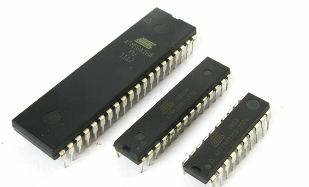
Just what is a microcontroller? To get you understand quickly I define a microcontroller as a single chip computer. Yes it is a full blown computer in its own. It has a C.P.U., RAM, some amount of EEPROM (for secondary storage i.e. permanent storage without power), many on-chip peripherals(Timer,Serial communication, Analogue to Digital converters etc.). If you don’t understand, no problem I will be dealing them in detail in next tutorials. But compared to a P.C. their resources(RAM,speed etc)are less. But that is what is required ! Because P.C. is a general purpose computer, which means it can run thousands of different software that are available for specific needs. Like it can run a game. The same P.C. can run this browser in which you are reading this! It can run a custom solution for banks,railways and airways. It can run a 3D modeling, video editing & image editing software for a production company. Many of these are huge software,requiring lots of memory and CPU power. And a P.C. can run simultaneously many of these ! So to run them the host computer should have enough RAM and CPU power so that it can run heaviest of them. But in case of a microcontroller(aka MCU) which is used for a specific purpose like switching a Microwave oven heating off after […]

ADC (Analog To Digital Converter) of AVR Microcontroller

Most of the physical quantities around us are continuous. By continuous we mean that the quantity can take any value between two extreme. For example the atmospheric temperature can take any value (within certain range). If an electrical quantity is made to vary directly in proportion to this value (temperature etc) then what we have is Analogue signal. Now we have we have brought a physical quantity into electrical domain. The electrical quantity in most case is voltage.To bring this quantity into digital domain we have to convert this into digital form. For this a ADC or analog to digital converter is needed. Most modern MCU including AVRs has an ADC on chip. An ADC converts an input voltage into a number. An ADC has a resolution. A 10 Bit ADC has a range of 0-1023. (2^10=1024) The ADC also has a Reference voltage(ARef). When input voltage is GND the output is 0 and when input voltage is equal to ARef the output is 1023. So the input range is 0-ARef and digital output is 0-1023. Fig: ADC Theory Inbuilt ADC of AVR Now you know the basics of ADC let us see how we can use the inbuilt ADC of AVR MCU. The ADC is multiplexed with PORTA that means the ADC channels are shared with PORTA. The ADC […]

Using Internal peripherals of AVR MCUs.

Each AVR MCU has several internal peripherals that give powerful abilities to your projects. For example internal ADC can be used to convert analog value (say voltage output of some sensor) to a digital value that you can use. And a USART(Universal Synchronous Asynchronous Receiver Transmitter) can be used to connect your MCU with PC. (Example use – A PC serial mouse or A PC controlled Toy Rocket Launcher). This tutorial gives you overview of the process used to interface with these peripherals. Internal peripherals. Now you know the basics of peripherals, lets see what peripherals are available in ATmega16 MCU. Two 8-bit Timer/Counters with Separate Prescalers and Compare Modes One 16-bit Timer/Counter with Separate Prescaler, Compare Mode, and Capture Mode Real Time Counter with Separate Oscillator Four PWM Channels 8-channel, 10-bit ADC 8 Single-ended Channels 7 Differential Channels in TQFP Package Only 2 Differential Channels with Programmable Gain at 1x, 10x, or 200x Byte-oriented Two-wire Serial Interface Programmable Serial USART Master/Slave SPI Serial Interface Programmable Watchdog Timer with Separate On-chip Oscillator On-chip Analog Comparator Interfacing Technique. Fig: Using internal peripherals of AVR MCUs. A peripheral is connected to MCU by some special registers. The different registers of any peripherals can be logically of two types- 1)Data registers – which usually contains some data, say byte received from USART or […]

Using LCD Module with AVRs

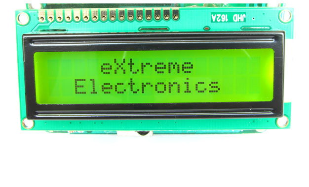
When you start working with LCD modules you will start feeling the real power of MCU and your imaginations will be touching sky you will wonder how many exciting a powerful gadgets you can create and that’s so very easily. LCD Modules can present textual information to user. It’s like a cheap “monitor” that you can hook in all of your gadgets. They come in various types. The most popular one can display 2 lines of 16 characters. These can be easily interfaced to MCU’s, thanks to the API( Functions used to easily access the modules) we provide. LCD interfacing is just fun ! Fig: A 16×2 LCD Module Buy LCD Modules Online In India   PIN Configurations. The lcd modules has 16 PINs for interfacing. The details are given below. LCD Module Pin Configuration 1 VSS (GND Supply) 2 VCC (+5V) 3 VEE (Contrast Adjust) 4 RS 5 R/W 6 E 7 DB0 8 DB1 9 DB2 10 DB3 11 DB4 12 DB5 13 DB6 14 DB7 15 LED + 16 LED –   Connection with ATmega8/ATmega168 etc. The lcd module can be easily connected to the any 28 pin AVR MCU like ATmega8/ATmega168/ATmega328 etc. The diagram below shows the LCD connection with AVR MCUs port pins. Fig: Connection with 28 PIN AVR MCUs Connect the required pins of […]

DC Motor Control using AVR MCUs

Motor gives power to your MCU. Ya power to do physical works, for example move your robot. So it is essential to know how to control a DC motor effectively with a MCU. We can control a DC motor easily with microcontrollers. We can start it, stop it or make it go either in clockwise or anti clock wise direction. We can also control its speed but it will be covered in latter tutorials. A Geared DC Motor. DC Motor A DC motor is electromechanical device that converts electrical energy into mechanical energy that can be used to do many useful works. It can produce mechanical movement like moving the tray of CD/DVD drive in and out (you may like to try it out Go to My Computer, right click the drive icon and click “Eject”). This shows how software controls a motor. DC motors comes in various ratings like 6V and 12V. It has two wires or pins. When connected with power supply the shaft rotates. You can reverse the direction of rotation by reversing the polarity of input. Control with AVR MCUs As the MCUs PORT are not powerful enough to drive DC motors directly so we need some kind of drivers. A very easy and safe is to use popular L293D chips. It is a 16 PIN […]