Tag Archives: pic16f877a

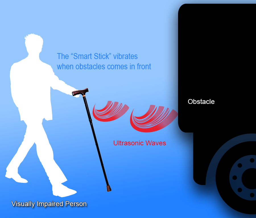
Obstacle Sensing Walking Stick for Visually Impaired Persons

This project is designed to guide a visually impaired person to walk and avoid bumping into obstacles. Low cost ultrasonic rangefinders along with a microcontroller is used to measure the distance to obstacles and if they are close enough provide a feedback to the user in form of beeps or vibrations. The project is made on a small single layer PCB. The sensors are not mounted on the PCB but they are mounted on front of the stick and connected to the main board using wires. All the parts of project PCB is shown in the image below. Read more … Pages Introduction and Usage Block Diagram Schematic and BOM PCB Layout Details of the Sensor Program and it’s Explanation

USART Library for PIC – Setup on MPLAB X IDE

This article describes the setup and use of the C library for serial communication. We focus on its usage with PIC16F series of MCUs from Microchip. Here we describe how to setup a MPLAB X project with support for serial communication related functions. The library is designed for compilation and use with Microchip’s XC8 C Compiler. Fig. Serial Communication Demo   Creating a New Project in MPLAB X You can create a new project using the MPLAB’s Start page as shown below. Fig. MPLAB X Start Page Alternatively you can use menu File->New Project Fig. Select New Project from File Menu And for those who love the Keyboard over mouse can hit <Ctrl>+<Shift>+<N> Any of the three method will launch the New Project Wizard as shown below. The first step is the selection of project type. From the Categories list select Microchip Embedded and from Projects select Standalone Project. Fig. Project Type Selection Second step is the selection of device for which the project is targeted. Select Mid Range 8-bit MCUs (PIC12/16/MCP) in Family and PIC16F877A in Device. Fig. Device Selection Third step is the selection of debug tool. For that select Simulator. Fig. Tool Selection Microchip MPLAB lets you install more that one compiler. It also lets you install more that one version of the same compiler. So their […]

Serial Communication with PIC16F877A

This article series aims at teaching serial communication between a PIC microcontroller and a PC. We first introduce you with what is serial communication is and how it can used. Then we tell you how to perform serial communication using PIC microcontroller and how we use the USART peripheral for the purpose. We will tell you how our usart library for PIC16F series can be used for easy serial communication, in this part we also discuss how to set up a MPLAB X project for using the USART library. After that we will build a demo project to explore the library. Finally we will burn this demo in a PIC16F877A and establish a serial communication with PC. Serial Communication Their are several serial communication standards like RS232, SPI, I2C etc. Of which RS232 is a asynchronous method. That means it does NOT have a synchronizing clock line. One way data requires only one conductor line. Since it is a two way communication their are two lines between the two device. One for sending data called the Tx and one for receiving data called the Rx. The communication is full duplex, that means data can be sent at the same time data is being received. generally other serial communication like SPI and I2C are used for short range communication like between […]

Making A Thermometer with PIC16F877A

At basic level on microcontroller you can create this interesting project of digital thermometer. It teaches you how to acquire analog data from a sensor and display it on a lcd. We will use a popular MCU PIC16F877A to implement this mini project. The temperature will be read using a LM35 precision sensor. Final result will be shown on a 16×2 alphanumeric lcd module. Fig. PIC16F877A Based Thermometer with LCD   Stuffs Required S. No. Item Image Cost 1 40 PIN PIC Development Board Rs. 769 2 16×2 LCD Board Rs. 296 3 Single PIN Burg Wires Female/Female 20 units Rs. 100 4 12V 1A DC Adapter Rs. 127 5 LM35 Rs. 60     Total Rs. 1,352 Connections The PIC16F877A development board has the PIC16F877A microcontroller chip and its supporting basic circuitry all in a nice high quality PCB. The development board comes fully assembled and tested, thus makes it ideal for doing experiments for learning by beginners. 40 PIN PIC Development Board In the bottom portion of the pic development board you can see a row of male headers. Most of these pins are the microcontrollers general purpose input/output lines and the rest are 5v and GND supply lines. Using these pins you can connect external peripherals (like the LCD board or something else) to do your experiment. […]

LCD Library for PIC – Setup on MPLAB X IDE

This article describes the setup and use of the C library for hd44780 based alphanumeric lcd modules. This library is also available for the AVR family of microcontrollers. This part is focused on its usage with PIC16F series of MCUs from Microchip. Here we describe how to setup a MPLAB X project with support for lcd related functions. The library is designed for compilation and use with Microchip’s XC8 C Compiler. Fig. LCD Demo   Creating a New Project in MPLAB X You can create a new project using the MPLAB’s Start page as shown below. Fig. MPLAB X Start Page Alternatively you can use File->New Project Fig. Select New Project from File Menu And for those who love the Keyboard over mouse can hit <Ctrl>+<Shift>+<N> Any of the three method will launch the New Project Wizard as shown below. The first step is the selection of project type. From the Categories list select Microchip Embedded and from Projects select Standalone Project. Fig. Project Type Selection Second step is the selection of device for which the project is targeted. Select Mid Range 8-bit MCUs (PIC12/16/MCP) in Family and PIC16F877A in Device. Fig. Device Selection Third step is the selection of debug tool. For that select Simulator. Fig. Tool Selection Microchip MPLAB lets you install more that one compiler. It also […]

Multiplexed Seven Segment Display using PIC16F877A and HI-TECH C

#include <htc.h> #define _XTAL_FREQ 20000000UL typedef unsigned char UINT8; typedef signed char INT8; typedef unsigned int UINT16; typedef signed int INT16; //Connection of Seven segment display #define SEVEN_SEGMENT_LAT PORTD #define SEVEN_SEGMENT_TRIS TRISD //MUX Control #define MUX_PORT PORTB #define MUX_START_POS 1 //From which bit on port the select lines start //MUX settings #define MUX_DISP_COUNT 4 //Number of displays //Global Varriable UINT8 DisplayArray[MUX_DISP_COUNT];//Holds ‘data’ for each disp void SevenSegmentWrite(UINT16 n) { /* n=data to dislay example: n=1234 will display 1234 in a 4 segment display Working: This function breaks apart a given integer into separete digits and writes them to the display array i.e. digits[] */ UINT8 i=0; UINT8 j; while(n) { DisplayArray[i]=n%10; i++; if(i==MUX_DISP_COUNT) break; //We don’t have room for more digits n=n/10; } //Fill Unused area with 0 for(j=i;j<MUX_DISP_COUNT;j++) DisplayArray[j]=0; } void WriteSegment(UINT8 num) { switch (num) { case 0: //-GFEDCBA SEVEN_SEGMENT_LAT = 0B01000000; break; case 1: //-GFEDCBA SEVEN_SEGMENT_LAT = 0B01111001; break; case 2: //-GFEDCBA SEVEN_SEGMENT_LAT = 0B00100100; break; case 3: //-GFEDCBA SEVEN_SEGMENT_LAT = 0B00110000; break; case 4: //-GFEDCBA SEVEN_SEGMENT_LAT = 0B00011001; break; case 5: //-GFEDCBA SEVEN_SEGMENT_LAT = 0B00010010; break; case 6: //-GFEDCBA SEVEN_SEGMENT_LAT = 0B00000010; break; case 7: //-GFEDCBA SEVEN_SEGMENT_LAT = 0B01111000; break; case 8: //-GFEDCBA SEVEN_SEGMENT_LAT = 0B00000000; break; case 9: //-GFEDCBA SEVEN_SEGMENT_LAT = 0B00010000; break; } } void Wait() { UINT8 i; for(i=0;i<1;i++) __delay_ms(10); } void main() […]