Tag Archives: sensor

Interfacing MMA7455 I2C Accelerometer with AVR ATmega8

This article on Digital Wizard describes everything about interfacing MMA7455 I2C accelerometer with an AVR ATmega8 MCU. A C library compatible with Atmel Studio 6 is also provide with step by step instructions to get it properly installed in your new AS6 project. Each function in the library is also explained in details. Finally we make a demo program to show raw acceleration readings for each axis on a LCD. Read more …

Remote Temperature Monitoring using GSM – AVR Project

If you want a live demo of this, please register from the link given below. (Only in Pune) REGISTER NOW! This project can also be implemented using a PIC18F4520 microcontroller. Temperature monitoring have wide application in daily life. In modern day keeping an eye on temperature of places such as server rooms, hospital rooms, warehouses and green houses can help solve many problems. But with the use of normal temperature sensors, someone needs to go to the place in order to view the temperature. But with the development of GSM network, one can easily connect the sensor with GSM network, so that you don’t need to be present near the sensor in order to view the temperature. You can just pick up your cell phone and send a request to your sensor by a text message and in no time you will receive the temperature of the remote place ! The advantage is the you don’t need any kind of "special" device at the receiver end. You can use any cell phone to view the remote temperature. This reduces cost as you already have a cell phone. Other benefit is that the range is not limited. You can be at any place in the world (with mobile coverage of course!), to request temperature data from your room. Fig. SMS Based […]

Interfacing TCS3200 Colour Sensor with AVR ATmega32

Detecting colour of an object can be an interesting and useful electronic application. It can be realized using a colour sensor like TCS3200 and a general purpose microcontroller like AVR ATmega32. TCS3200 Colour Light to Frequency Converter Chip Fig. TCS3200 Chip .   TCS3200 chip is designed to detect the colour of light incident on it. It has an array of photodiode (a matrix of 8×8, so a total 64 sensors). These photodiodes are covered with three type of filters. Sixteen sensor have RED filter over them thus can measure only the component of red in the incident light. Like wise other sixteen have GREEN filter and sixteen have BLUE filter. As you should know that any visible colour can be broken into three primary colours. So these three type of filtered sensors helps measure the weightage of each of primary colours in incident light. The rest 16 sensors have clear filter. TCS3200 converts the intensity of incident radiation into frequency. The output waveform is a 50% duty cycle square wave. You can use the timer of a MCU to measure period of pulse and thus get the frequency. The output of TCS3200 is available in single line. So you would ask how we get the intensity of RED,GREEN, BLUE and CLEAR channels? Well it has two inputs S2 and […]

Making a Line Sensor using IR Receiver

A line follower robot, or a LFR in short, is a simple autonomous robot that optically tracks a line made on the surface of the floor. That means you have an arbitrary line drawn on the floor and the robot tracks it by moving right along it! The line is sensed using a piece of hardware called a line sensor. A line sensor can be easily made using a low cost IR Rx/Tx pair. The IR Rx emmits IR radiation and the Rx helps in receiving the waves. See the figure below for working of line sensor. Working of Line Sensor Schematic for Line Sensor. Line Sensor Schematic   Actual IR Rx Tx Pair. Line Sensor Array. Actually a group of such sensor units as described above is required to make a line follower robot. We generally use 3 or 5 such sensor unit to make a line sensor array. The complete steps are described below. You need small piece of veroboard (general purpose PCB). Actual IR Rx Tx Pair. We will fit the sensor at the castor mount of the metal chassis. So we carefully mark the location we need drilling. Mark drilling location.   Mark the drilling location. You can make the hole easily by using a pair of scissor. Just press and rotate. Make hole using scissor. […]

Digital Humidity Sensor

Digital Humidity sensors are of great help in maintaining suitable environmental condition in places such as ware houses, green houses, factories, smart homes etc. They are also very easy to interface with MCU and PC. When coupled with a PC or Microcontroller they can be used in wide variety of smart automation. One such sensor I will present today is a serial humidity sensor. The interface is very simple. The communication is done over a standard asynchronous serial line. The interface parameters are as follows. UART 9600 bps. Start bit: 1 Stop bit: 1 Parity Bit : 0 (No parity bit) No Flow Control. Fig.: Serial Humidity Sensor.   Command Set All commands are begin by "$sure" followed by space (ascii 32) All UART Command are in ASCII Commands are NOT case sensitive. All commands ends with a CR LF pair (ascii \r\n in C language). Get Current Temperature in Degree Centigrade Command : $sure temp -c Returns: XXXCentigrade Where XXX is current temperature. Example in C UWriteString("$sure temp -c\r\n"); Get Current Temperature in Degree Fahrenheit Command : $sure temp -f Returns: XXXFahrenheit Where XXX is current temperature. Example in C UWriteString("$sure temp -f\r\n"); Get Current Humidity Command : $sure humidity Returns: XXX%RH Where XXX is current relative humidity. Example in C UWriteString("$sure humidity\r\n"); Get Current Status Command : $sure […]

Interfacing LM35 Temperature Sensor with PIC Microcontroller.

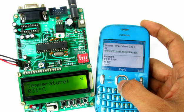
The are many cool sensors available now a days, ranging from IR distance sensor modules, accelerometers, humidity sensors, temperature sensors and many many more(gas sensors, alcohol sensor, motion sensors, touch screens). Many of these are analog in nature. That means they give a voltage output that varies directly (and linearly) with the sensed quantity. For example in LM35 temperature sensor, the output voltage is 10mV per degree centigrade. That means if output is 300mV then the temperature is 30 degrees. In this tutorial we will learn how to interface LM35 temperature sensor with PIC18F4520 microcontroller and display its output on the LCD module. First I recommend you to go and read the following tutorial as they are the base of this small project. Interfacing LCD Module with PIC Microcontrollers. Making the LCD Expansion Board for PIC18F4520. Using the ADC of PIC Microcontrollers. After reading the ADC tutorial given above you will note the the PIC MCU’s ADC gives us the value between 0-1023 for input voltage of 0 to 5v provided it is configured exactly as in the above tutorial. So if the reading is 0 then input is 0v, if reading is 1023 then input is 5v. So in general form if the adc read out is val then voltage is. unsigned int val; val=ADCRead(0); //Read Channel 0 voltage= […]

Obstacle Avoiding Robot using AVR ATmega32 – Part II

Hello and Welcome back to the second part of Obstacle Avoiding Robot Tutorial. In the last part we studied the drive system and the mechanical construction of our robot. In this part we will make the sensor part. The sensors will help our robot detect obstacle in its path. The sensor system is of very basic type of infrared(IR) reflectance sensor. It is made up of an IR Transmitter and an IR receiver. The IR transmitter is an IR LED which emits light in IR spectrum that is invisible to human eye. The IR receiver can detect those rays. A Matching Pair of IR Rx and Tx, The Blue One is Tx (LED). The IR Sensor Element The IR Sensor element is made up of an IR Tx,IR Rx and few resistors. The schematic is given below. We need three such elements mounted in front of the robot to sense obstacles in front of it. IR Reflectance sensor schematic. As you can see the sensor element has two pins for power supply and an Output pin. The output is a variable voltage between 0 and 5v depending on the type and distance of the obstacle. It tends to 5v as some obstacle comes near it. IR Sensor Construction Guidelines. The value of R1 is 150 ohms and R2 is 22K. […]