Tag Archives: Seven Segment

High Power Multiplexed Seven Segment LED Display Driver

One of the most common place where small MCUs are used is to drive big seven segment displays in public area. For example the bank token number, flight or train schedule, train coach number, production volume (in factories), current forex(in banks) or gold rates etc. Since these are public display they should be big (and bright) enough to be seen from a distance of few meters. And due to their bigger size(and high brightness) they require 12V supply for each segments. Current requirement is also high. All these call for a sophisticated circuit, since these type of circuit is very common we have developed a compact board with integrated high voltage driver circuit coupled with an AVR 8 bit CPU. High Voltage Seven Segment Display Driver Board Further information, datasheet and user manual will be available as soon as the product is offered for sale. More Images

Thermometer with PIC Microcontroller

In the last tutorial we learn about the multiplexing technique used with seven segment displays. We learnt how it saves i/o line by using persistence of vision. Only one digit is lit at a time, but to a human eye it is too fast to catch, so we see all four digit lit the same time. In this tutorial we will make a practical use of multiplexed seven segment displays. We will use them to show current room temperature using a LM35 temperature sensor. Before reading further make sure you know the following concepts Multiplexing Seven Segment Display with PIC Micro. Using ADC of PIC Micro. Interfacing LM35 temperature sensor with PIC Micro. Schematic for PIC Thermometer Please note that this schematic is slightly different from our previous schematic on multiplexed seven segment display. The display select i/o pins were RA0,RA1,RA2,RA3 on that schematic. But in this schematic the display lines are RA1,RA2,RA3,RA4 this is because RA0 is used as analog input channel for LM35’s output. PIC Thermometer using LM35   Multiplexed Seven Segment wiring We use our PIC Development Board for making the above demo project. The PIC Development Board has all the core circuitry to sustain the MCU while the project specific part is developed on the expansion board. Multiplexed Seven Segment Display Setup   Multiplexed Seven Segment […]

Using Multiplexed 7 Segment Displays – PIC Microcontroller Tutorial

A four digit seven segment display. The image above shows a four digit seven segment display. These type of displays are widely used to present numerical data to users. Example includes clocks, panel meters, microwave ovens, refrigerators etc. As you can see in a four digit displays there are a total of 4 x 7 = 28 segments (made of leds) so you may think that they will require lots of i/o pins of MCU. But in reality a small trick can greatly reduce the number of i/o pins required. The trick is to activate only one digit at a time. All the segments of each four digit are connected in parallel and common of each four digit is tried to MCUs i/o port via transistors. That means MCU can select any digit and put the segment data which drives the segments. Only the selected digit will light up. Then next digit is selected and segment data is changed according to the digit that must be shown in that place. Similarly each digit is selected and shown. This is done fast enough that the human I cannot see the movement. We can see all four digit lit at the same time as shown in the figure above. Multiplexed Seven Segment wiring To display any four digit number, say 1234 on […]

Multiplexed Seven Segment Display using PIC16F877A and HI-TECH C

#include <htc.h> #define _XTAL_FREQ 20000000UL typedef unsigned char UINT8; typedef signed char INT8; typedef unsigned int UINT16; typedef signed int INT16; //Connection of Seven segment display #define SEVEN_SEGMENT_LAT PORTD #define SEVEN_SEGMENT_TRIS TRISD //MUX Control #define MUX_PORT PORTB #define MUX_START_POS 1 //From which bit on port the select lines start //MUX settings #define MUX_DISP_COUNT 4 //Number of displays //Global Varriable UINT8 DisplayArray[MUX_DISP_COUNT];//Holds ‘data’ for each disp void SevenSegmentWrite(UINT16 n) { /* n=data to dislay example: n=1234 will display 1234 in a 4 segment display Working: This function breaks apart a given integer into separete digits and writes them to the display array i.e. digits[] */ UINT8 i=0; UINT8 j; while(n) { DisplayArray[i]=n%10; i++; if(i==MUX_DISP_COUNT) break; //We don’t have room for more digits n=n/10; } //Fill Unused area with 0 for(j=i;j<MUX_DISP_COUNT;j++) DisplayArray[j]=0; } void WriteSegment(UINT8 num) { switch (num) { case 0: //-GFEDCBA SEVEN_SEGMENT_LAT = 0B01000000; break; case 1: //-GFEDCBA SEVEN_SEGMENT_LAT = 0B01111001; break; case 2: //-GFEDCBA SEVEN_SEGMENT_LAT = 0B00100100; break; case 3: //-GFEDCBA SEVEN_SEGMENT_LAT = 0B00110000; break; case 4: //-GFEDCBA SEVEN_SEGMENT_LAT = 0B00011001; break; case 5: //-GFEDCBA SEVEN_SEGMENT_LAT = 0B00010010; break; case 6: //-GFEDCBA SEVEN_SEGMENT_LAT = 0B00000010; break; case 7: //-GFEDCBA SEVEN_SEGMENT_LAT = 0B01111000; break; case 8: //-GFEDCBA SEVEN_SEGMENT_LAT = 0B00000000; break; case 9: //-GFEDCBA SEVEN_SEGMENT_LAT = 0B00010000; break; } } void Wait() { UINT8 i; for(i=0;i<1;i++) __delay_ms(10); } void main() […]

Multiplexed Seven Segment Displays – Part II

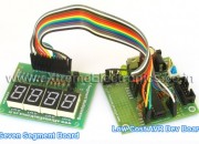
Hi Friends, In last tutorial we discussed about Multiplexing Seven Segment Displays. So you must be very much familiar with the theory. Now let us write the code and design a small project that will make you expert in using these displays in your own projects. We will make a system that can display any number between 0-9999 using four of these displays. We will design a function Print() that we can use on latter projects to easily write integers onto displays. Once we have successfully tested this function we can add to to any project without any problem. This concept of code reuse will make bigger project both easy to make and far less painful. In this sample project we will test our function by using it in a loop to print all numbers from 0-9999. for(i=0;i<10000;i++) { Print(i); Wait(); } Things Required S. No. Item Image 1 28 PIN AVR Dev Board Contains the core AVR circuit including 5v regulator, reset, ISP. 2 Seven Segment Display Module Four common anode displays multiplexed with driver transistors and current limiting resistors. 3 Single Pin Female to Female Burg Wires Used to interconnect the two boards   4 USB AVR Programmer To upload the program to the development board. These are all the things required to get started with seven segment […]

Multiplexed Seven Segment Displays.

We have discussed the basics of seven segment displays on our tutorial “Using Seven Segment Displays with AVR MCUs”. So you should be familiar with them. In this tutorial we will discuss about multiplexing of seven segment displays.Multiplexing is required when we want to interface 3 or 4 or even more such displays with MCUs since it we go for normal way it will require lots of IO port. So the smart way is multiplexing. Multiplexing achieved by tricking our eyes. Only one display is active at a time but we see all of them active. For multiplexing all the displays are connected in parallel such that if you activate any segment, say ‘a’ the ‘a’ segment of all displays glows up. But the trick is that we can switch on and off the “common” line of the displays under MCU control. So if we wish to light up the ‘a’ segment of display 2 we simply switch on display 2 first by applying proper level at the base of its driving transistor as shown in figure. Fig – Multiplexed Seven Segment Displays. If we like to display the digit say “123” on three displays first we select disp-3 by applying a “low” level at the base of transistor Q1 and output the code of required digit at the data […]

Interfacing Seven Segment Displays

Seven segment displays are very common for electronic product to display numerical output. Many common devices like calculators, watches, electronic weighing scales,ovens etc use them. You must have also seen lifts display the current floor numbers in seven segment displays. So in this article I will show you how to use 7-Segment displays in your own projects. Fundamentals A seven-segment display is so named because it is divided into seven different segments that can be switched on or off. The different combination of these segments switched on produces different English numbers. The display also has a decimal point.   Fig: Seven Segment Display Fig: ‘4’   The figure shows a seven segment display and the names of the various segments. For example if you want to display number 4 then segments that will be ‘on’ are {f,g,b,c} while rest are ‘off’.Basically the seven segments are just LEDs. The one common end of all the leds are connected while the rest are available. Depending on whether anode or cathode of all the leds are common they are of two types. 1) Common anode 2)Common cathode Fig: Common Cathode Type Fig: Common Anode Type PIN Configuration Now you know the basic of these displays, to use them you should know the pin configuration of the commercially available displays. As you must have […]