Mechanical Construction
AVR ATmega8 Based Line Follower.
Easy to make PID LFR Robot.
The kit comes with the following components.
- High Quality Acrylic Chassis 1 unit.
- 150 RPM Gear Motor 2 units.
- 7cm x 2cm Plastic Wheels 2 units.
- Castor Wheel 1 units.
- Main Board 1unit.
- Sensor Board 1unit.
- FRC Cable to connect sensor board with main board 1unit.
- Battery Holder 1unit.
- 2 PIN Power Supply Relimate Connecter 1unit.
- Black Plastic Spacer to provide space between board and chassis 4 units.
- Screws and nuts.
Mounting The Motors
We provide two 150RPM (or 200 RPM) gear motor with the kit.
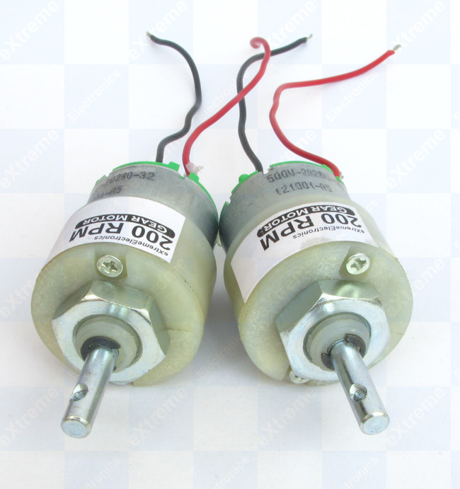 |
Fig. 1 - Geared DC Motors. |
Remove the nut of the motor.
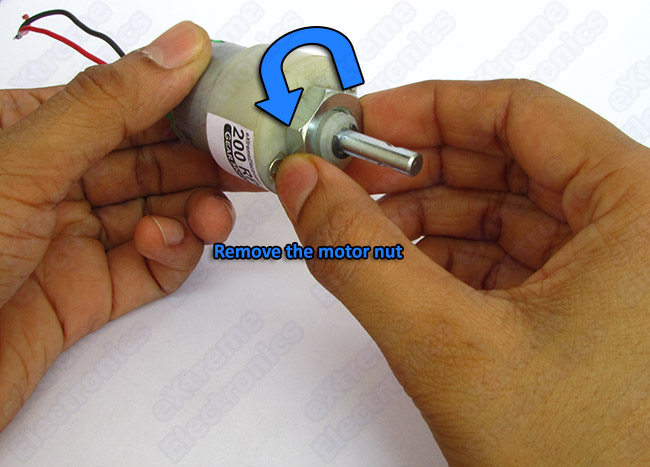 |
Fig. 2 |
Insert the motor in the motor clamp.
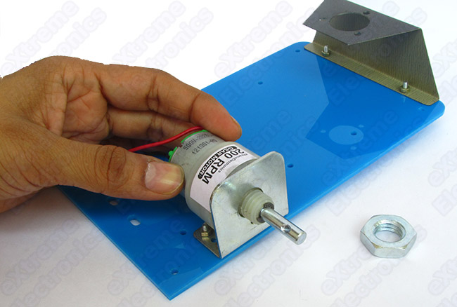 |
Fig. 3 |
Fasten the nut.
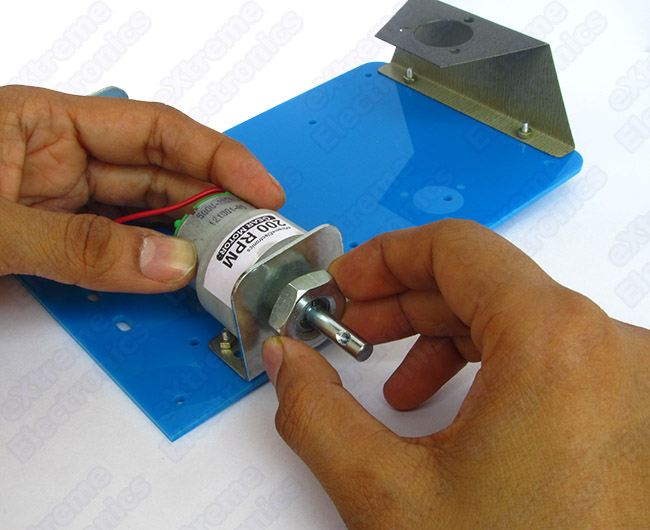 |
Fig. 4 |
Similarly mount the second motor.
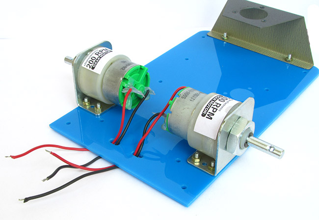 |
Fig. 5 |
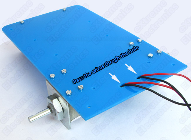 |
Fig. 6 |
Mounting the main board.
The main board has four holes to mount it on the chassis.
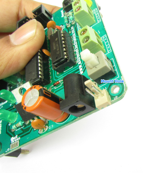 |
Fig. 7 - Mount Hole |
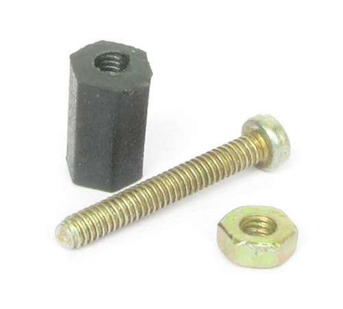 |
Fig. 8 - Mounting Kit. |
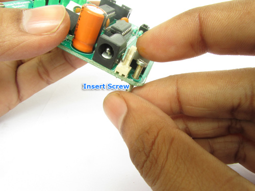 |
Fig. 9 - Insert Screw |
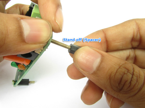 |
Fig. 10 - Attach Standoff |
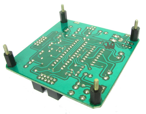 |
Fig. 11 - All stand off connected. |
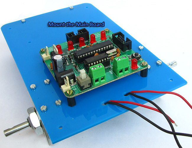 |
Fig. 12 - Mount the main board. |
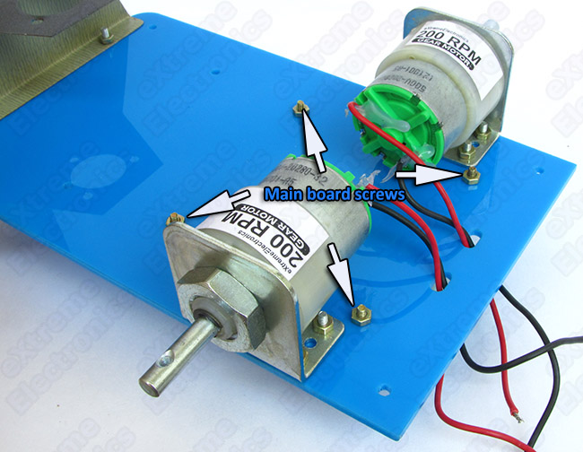 |
Fig. 13 - Secure the board using nut. |
Unscrew the motor connection points in the main board.
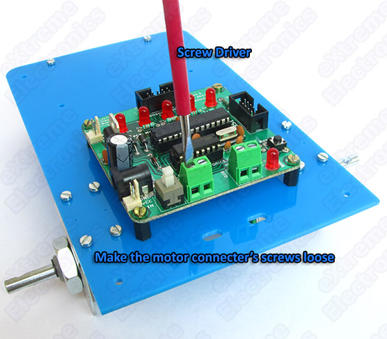 |
Fig. 14 |
Insert the motor's wires into the connecter holes as shown below. Please makes sure wires are inserted according to their colour. Which colour goes to which side is marked on the PCB. Also make sure left motor's wires are connected to the LEFT motor's connecter only ! Similarly right motor's wires are connected to RIGHT motor connecter. This is also marked on PCB
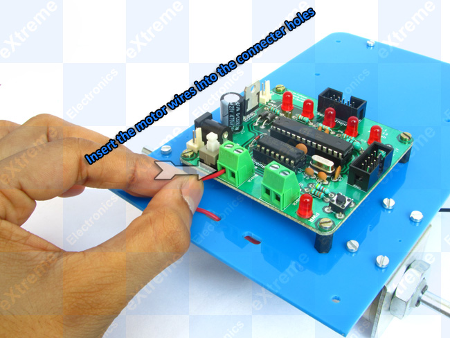 |
Fig. 15 |
After inserting all four wires the screws of the connecter should be made tight again. This will hold all wires on their place. Finally it should look like this.
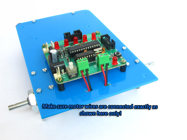 |
Fig. 16 |
Mounting the Wheels
The KIT comes with 2 units of plastic wheels which have a diameter of 7cm.
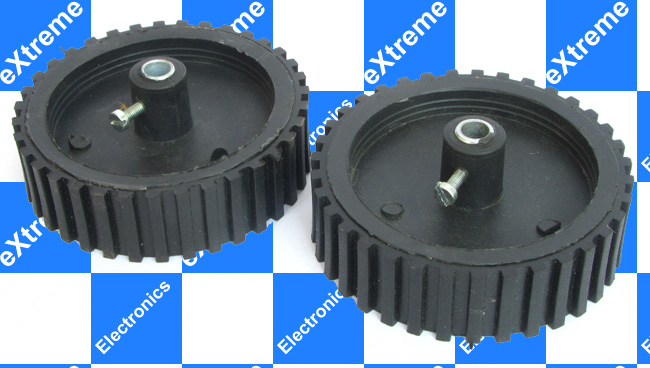 |
Fig. 17 |
First make the screw of the wheel loose and then slide them over motor's shaft.
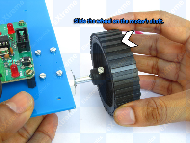 |
Fig. 18 |
Finally fasten the screws.
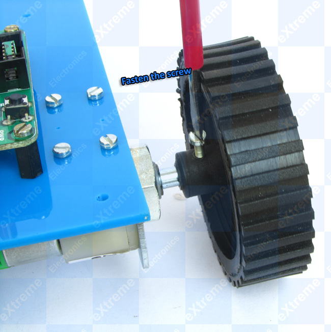 |
Fig. 19 |
Mounting the Line Sensor Board and Caster Wheel.
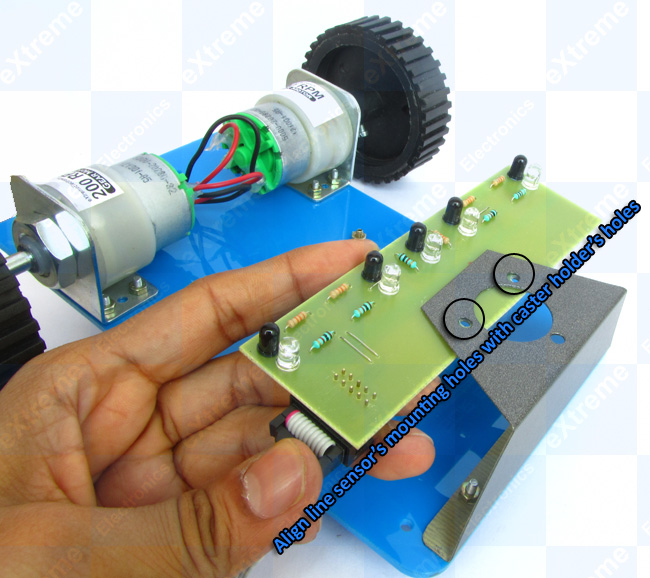 |
Fig. 20 |
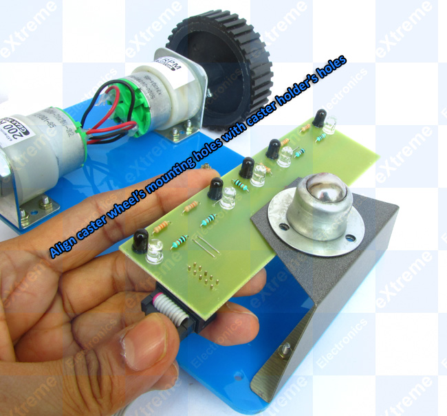 |
Fig. 21 |
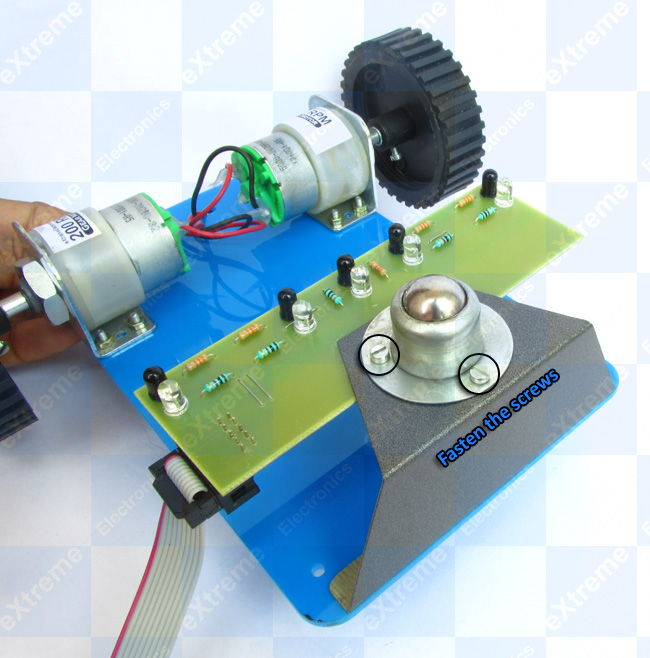 |
Fig. 22 |
Cell Holder
Our line following robot is powered by 6 units of AA Cell. The standard 1.5V AA Cells are placed on a cell holder to form a 9V Supply. The cell holder makes it easy to insert and remove the cells.
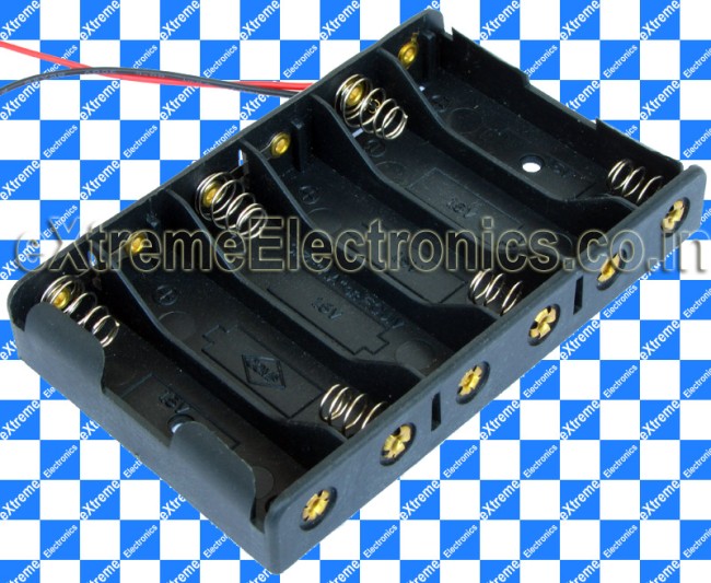 |
Fig. 23 - Cell Holder |
Their are two holes in the cell holder to fix it on to the chassis. Their are also two holes in the chassis where you can fix the cell holder using screws and nuts.
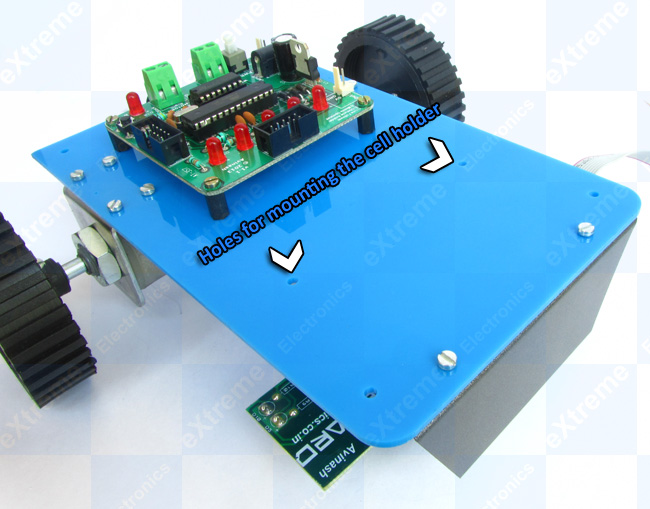 |
Fig. 24 - Holes for mounting the cell holder |
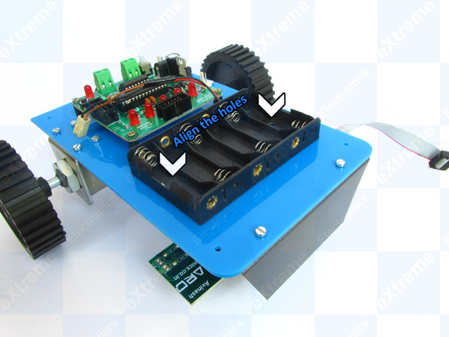 |
Fig. 25 - Align the holes |
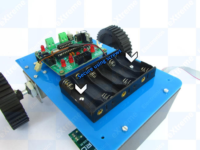 |
Fig. 26 - Secure using screws |
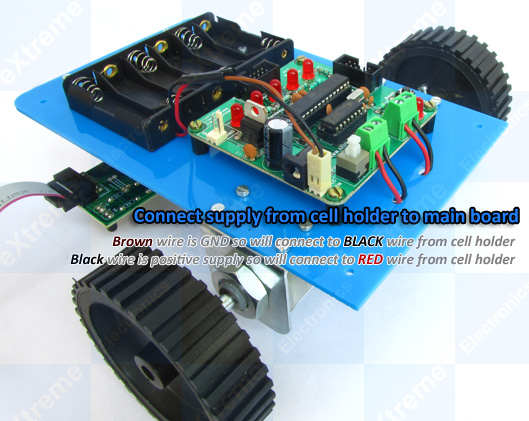 |
Fig. 27 - Connect power supply |
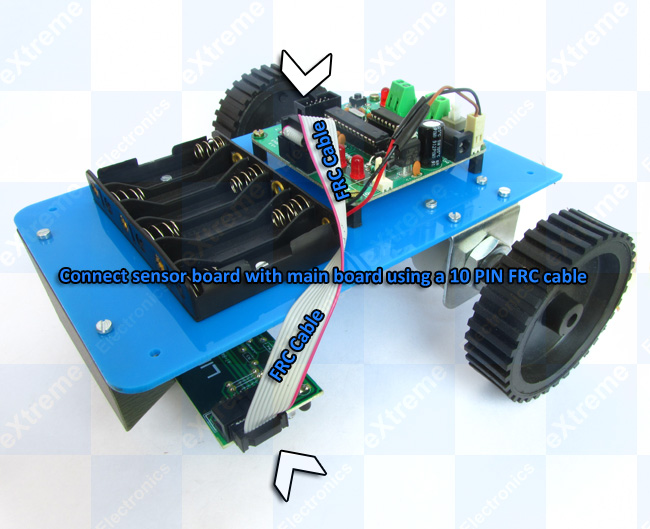 |
Fig. 28 - Connect sensor board with main board |
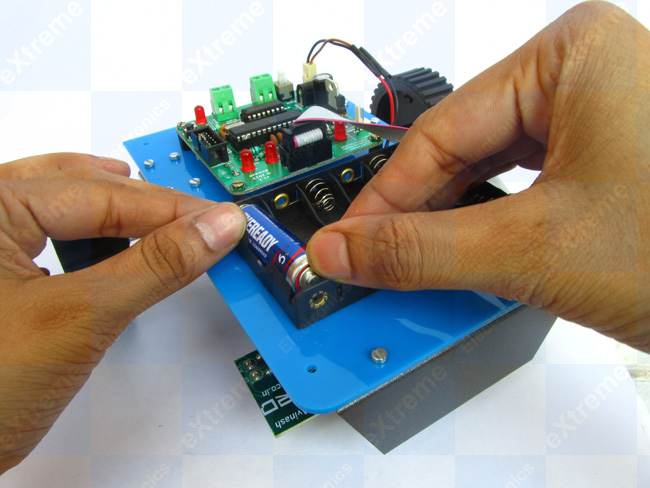 |
Fig. 29 - Insert 6 cells |
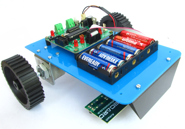 |
Fig. 30 - Finished ! |
Return to Help Index.