Input-Output Ports
AVR ATmega8 Bases Line Follower.
Easy to make PID LFR Robot.
Introduction
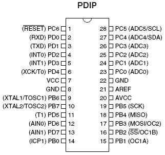
Digital IO is the most fundamental mode of connecting a MCU to external world. The interface is done using what is called a PORT. A port is the point where internal data from MCU chip comes out or external data goes in. They are present is form of PINs of the IC. Most of the PINs are dedicated to this function and other pins are used for power supply, clock source etc as you have seen in Part III of my tutorials. Ports are named PORTA, PORTB, PORTC, PORTD etc. The pin configuration of ATmege8 mcu is shown below
 |
Fig - Mege8 pin configuration |
As you can see the pins are labeled PC6,D0,PD1…etc . A port say PORTD is a 8bit register you can set it to any value like
PORTD=0xFF;
In C language prefix 0x signifies a hexadecimal number here 0xFF means decimal 255 or binary 11111111 which means all the bits in the register is high. A high value on the output port gives +5V and 0 gives ground. You can set the value of PORTD to any required value. This is the basic of digital interface. You can connect LEDs, and switch them on/off from your program. You can connect speaker and produce desired frequency by quickly switching the PORT pin on/off to get sound. But these PORT can source and sink limited current that means you cannot directly connect devices that need heavy current. But by use of proper hardware you can interface power demanding devices like motors and relay. By the use of proper relays you can control device of any voltage, current and power like a huge mains water pump!
These digital IO pins can also be used to read in the data from external world. In simplest case you can use them to read the state of switch or sensors. This way you can make a keypad for your device.Using AVRs digital IO pins.
As I said each AVR MCU has several IO ports named A,B,C etc. You can find out their physical location by looking at the pin configuration given above. For example Port C’s 0th bit is at PIN 23 of the IC. You must have also noticed that there are additional names given in brackets near the PINs. This is due to the fact that IO pins have more than one function. The primary and the default is given near the pin while the secondary and tertiary functions are given in brackets. The secondary functions are huge life saver for us. This is where these chips starts showing their power.
Additional Port Functions
Basically any digital IO is carried by 1s and 0s that we can do with simply accessing the PORTs then why secondary functions? Yes, you can make any functionality(ex serial data transfers etc) in software by simple manipulating the PINs or reading their values. But that “common task” which is commonly required in MCU world are already implemented for you and that’s too in hardware. Yes, the AVR MCU has several inbuilt hardware called the peripherals.
- USART for serial communication with PC and other devices. Example uses -A robots controlled by PC and connected to it using only 3 wires. -A digital room thermometer that logs daily temperature and can be connected to PC to view the records in special software
- ADC-Analog to digital converter used for advance sensor interfacing Example uses -Reading the value of temperatures or amount of light falling on a sensor.
- SPI- Serial peripheral interface. It is used for serial communication between digital devices(EEPROMs, Data Flash, LDC modules etc)
- Output compare pins can be used to generate digital wave forms automatically. They are highly configurable. Example uses - Controlling speed of DC motors. - Simple sound and frequency generation without making the CPU busy. CPU just sets the desired frequency and is free to do other things and the hardware does it all.
There are many other functions to help you I have just touched the surface here to just get you an idea. More about them in next tutorials.
Accessing digital IO in C
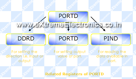
Each PORT in AVR has three related Registers.
 |
Fig - PORT D's related registers. |
DDRD: This is the Data Direction Register of PORTD. The bits in this register set the data direction of individual pins. The direction for each pin can be input or output. Port pins are made input when you want to read data from them ex a light sensor. They are made output when you want to use them to output data ex blink led or control a motor. To set any pin as output set its bit to ‘1’ and to make it input make it ‘0’.
For example …
//Make portd-0 as output
DDRD=0b00000001;
In this example portd’s 0th bit is made output while rest pins are input.By default all IO port pins are input i.e. ‘0’
PORTD: After you have set the pins to output now you can control them with is register the values you write here will be visible on the related pins of the MCU. For example
…//Make portd-0 high
DDRD=0b00000001;
//Wait one sec
Wait(1);
//Make it low
DDRD=0b00000000;
…
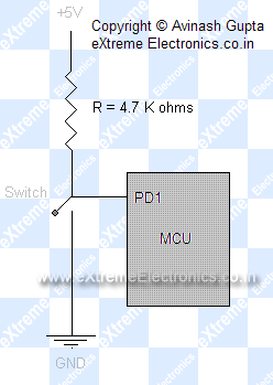
PIND - Port Input : When you set any port pin as input you have to read its status using this register. Suppose you have connected a switch as shown below
 |
Fig - Interfacing a swictch to an Input PORT. |
then as the ports are initially input type then you need no initialization. You can read the state of key/switch by simply reading the PIND. It will be ‘1’ when un pressed and ‘0’ if pressed. Sample code
...
if(PIND && 0b00000010)
{
 //Switch is not pressed
 ...
}
else
{
 //Switch pressed
 ...
}
...
If you don’t get the line if(PIND && 0b00000010) then you need to improve your C skills see Yashwant Kanetkars great book “Let us C” it has a chapter on operation on bits. Also check out my brothers blog http://learning-computer-programming.blogspot.com it is a great place to learn basic C/C++ programming.
The above example told you how to take input from real world using sensors or switches.
Now you know the basics of digital IO in AVR MCUs which is very fundamental topic in MCU world. The concepts will be used in any projects you go for.
Return to Help Index.