Know Your Board.
AVR ATmega8 Based Line Follower.
Easy to make PID LFR Robot.
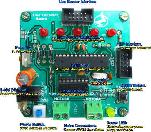
The basic parts of the board are explained below.
Board Overview (Click to Enlarge ...). |
- Line Sensor Interface: Direct connection of a 5 Channel Line Sensor Module using a 10 PIN FRC Cable.
- Line Sensor Status LEDs: 5 LEDs one for each channel of line sensor module. LED on indicates a line is detected under the associated line sensor channel. More Details.
- ISP Interface: For program download using an ISP Programmer. See this article for more information.
- RESET Button: Resets the current running program to start from the beginning.
- MOTOR A: Right Motor connector.
- MOTOR B: Left Motor connector.
- Power Switch: Turns on/off the board.
- DC Input: Main power supply to the board. Recommended supply is from 6x AA Cells which gives 9V DC Input. Or you can use a 12V 1A DC Adaptor. The adaptor type should be center positive.
- Out: 5V regulated power supply output to supply external peripherals.
Return to Help Index.
