Hello All,
Today I will show you how you can make a simple RPM Meter using AVR ATmega8. The RPM meter we will be making is a contact less type, i.e. it measures the RPM of a rotating object without actually making any contact with it. An IR reflectance sensor will be used to sense the speed. You have to attach a white reflective object (like a white paper sticker) at one point in the periphery of rotation . Then you need to place the reflectance sensor such that the white reflector comes just above it once per rotation. In this way the sensor will give one falling edge to the MCU per rotation, we will measure number of such pulse in one second to get the revolution per second, multiplying this with 60 we get RPM.
For this project I will use a ATmega8 MCU connected to a 16×2 LCD Module for showing the RPM.
Design of AVR based RPM Meter.
The sensor part is made up of TCRT5000 IR Reflectance sensor. It it wired as shown below. The sensor will give a LOW output whenever it detects a white reflective surface just above it. This output is feed to the INT0 pin of MCU. INT0 is a general purpose external interrupt source. It can be adjusted to interrupt the CPU on Rising, falling, low level or high level. In this project we configure it to interrupt on falling edge. When ever a falling edge (high to low transition) is detected on INT0 pin the CPU jumps to the ISR which handles the even. The ISR just increments a global variable count, in this way we keep track of number of revolution.
TIMER1, which is a 16 bit counter is used to generate an interrupt each second. On TIMER1 ISR we just copy the value of count to another global variable rps. And clear count to zero. The input to TIMER1 is taken by prescaler which is set at 1:1024, that means TIMER1 is clocked at 1/1024 of system clock. As our system clock is 1000000, timer frequency is 1000000/1024=976 Hz. To get exact 1 sec time base we use the comparator unit of timer, we set compare value to 976. So as soon as TIMER1 reaches 976 it is cleared to 0 (CTC mode) and an interrupt called output compare 1A (1 because it is timer1 and A because timer1 has 2 comparator A and B)
In the main loop of the program we just print RPM and RPS.
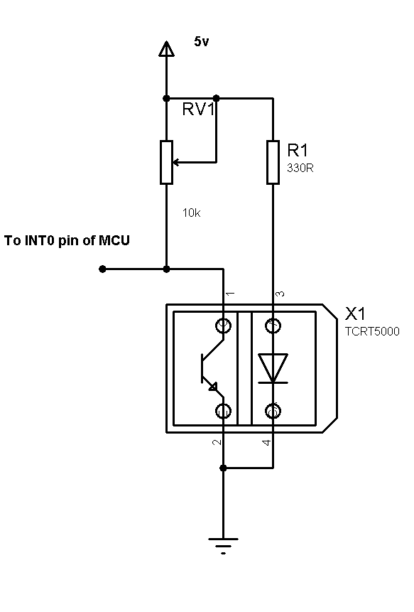 |
Fig.: TCRT5000 reflectance sensor. |
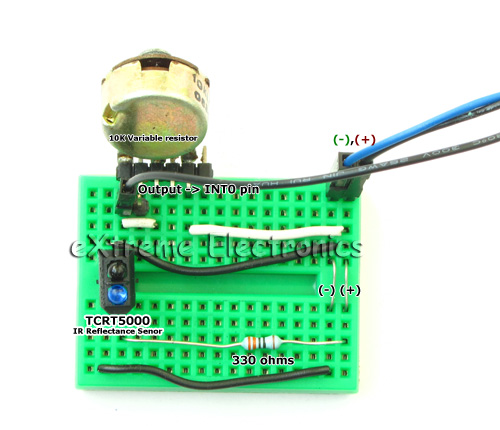
The above circuit made on a mini bread board.
Fig.: TCRT5000 reflectance sensor. |
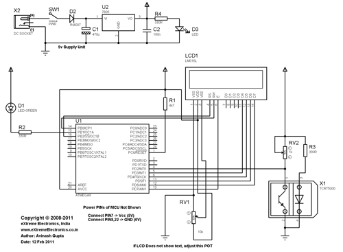
Schematic of AVR based RPM Meter
Fig.: Complete Schematic (Click to Enlarge) |
AVR GCC code for RPM Meter.
#include <avr/io.h>
#include <avr/interrupt.h>

#include <util/delay.h>

#include "lcd.h"

volatile uint16_t count=0;    //Main revolution counter

volatile uint16_t rpm=0;   //Revolution per minute

volatile uint16_t rps=0;   //Revolution per second


void Wait()
{
   uint8_t i;
   for(i=0;i<2;i++)
   {
      _delay_loop_2(0);
   }
}


void main()
{
   LCDInit(LS_NONE);

   LCDWriteString("RPM Meter");
   LCDWriteStringXY(0,1,"- by avinash");

   Wait();
   Wait();
   Wait();
   Wait();

   //Init INT0
   MCUCR|=(1<<ISC01);   //Falling edge on INT0 triggers interrupt.

   GICR|=(1<<INT0);  //Enable INT0 interrupt

   //Timer1 is used as 1 sec time base
   //Timer Clock = 1/1024 of sys clock
   //Mode = CTC (Clear Timer On Compare)
   TCCR1B|=((1<<WGM12)|(1<<CS12)|(1<<CS10));

   //Compare value=976

   OCR1A=976;

   TIMSK|=(1<<OCIE1A);  //Output compare 1A interrupt enable

   //Enable interrupts globaly
   sei();

   //LED Port as output
   DDRB|=(1<<PB1);


   LCDClear();

   LCDWriteStringXY(0,0,"RPM =");
   LCDWriteStringXY(0,1,"RPS =");

   while(1)
   {
      LCDWriteIntXY(6,0,rpm,5);
      LCDWriteIntXY(6,1,rps,5);

      if(PIND & (1<<PD2))
      {
         PORTB|=(1<<PB1);
      }
      else

      {
         PORTB&=(~(1<<PB1));
      }

      Wait();
   }

}

ISR(INT0_vect)
{
   //CPU Jumps here automatically when INT0 pin detect a falling edge
   count++;
}

ISR(TIMER1_COMPA_vect)
{
   //CPU Jumps here every 1 sec exactly!
   rps=count;
   rpm=rps*60;
   count=0;
}
The above code can be compiled using avr-gcc (WinAVR distro) and AVR Studio. Details about downloading, installing and using the software is described in the following tutorial.
The code depends on the LCD Library for displaying textual/numeric data on a standard 16×2 LCD Module. The file "lcd.c" must be copied to the project folder and added to the project using AVR Studio. See LCD Tutorial for more info. Compatible lcd.c and lcd.h files are provided at the bottom of this article.
After compiling the code, burn it to the MCU using an AVR Programmer. The Fuse bits must be set as follows.
- HIGH=D9
- LOW=E1
Please note that the above is default for ATmega8, so if you purchased a new chip then you do not need to change them. But if you have purchased xBoard MINI v2.0 then you need to write the above fuse bytes, as xBoard MINI v2.0 used different configuration.
Testing the RPM meter.
After powering on the system adjust variable resistor RV1 until the LCD start showing up some text. Then bring the reflective surface above the sensor and adjust RV2 until LED D1 start glowing. Once LED start glowing move the reflective surface away from the sensor, the LED should turn off. Now the system is ready to measure the RPM.
I have used a small 12v motor to test, I have attached a small fan onto the motor.
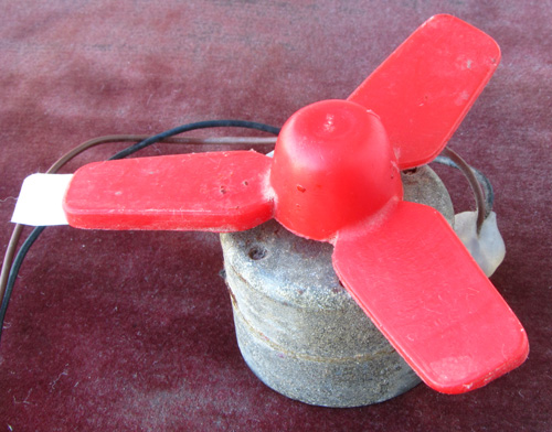 |
Fig.: A small motor with Fan. |
One of the blade of the Fan has a white paper sticker.
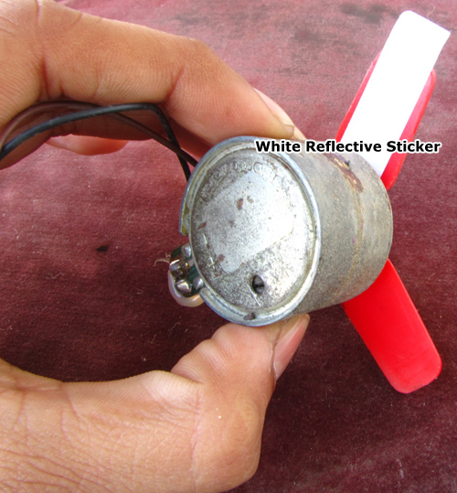 |
Fig.: Reflector on Blade |
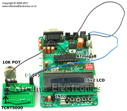
I have use xBoard MINI v2.0 as the development board. So I don’t have to wire up the entire circuit. The power supply, LCD and MCU core (and much more) are pre-built.
Fig.: RPM Meter Built using xBoard MINI v2.0 |
Downloads
- Complete AVR Studio Project (With compatible LCD Lib)
- HEX File ready to burn.
Help Us!
We try to publish beginner friendly tutorials for latest subjects in embedded system as fast as we can. If you like these tutorials and they have helped you solve problems, please help us in return. You can donate any amount as you like securely using a Credit or Debit Card or Paypal.
We would be very thankful for your kind help.
By
Avinash Gupta
Facebook,
Follow on Twitter.
www.AvinashGupta.com
me@avinashgupta.com
Facing problem with your embedded, electronics or robotics project? We are here to help!
Post a help request.



Fantastic, Just the thing I needed to understand, I must go through the code thoroughly, Thanks Avinash, Keep it up !
Mr. Avinash,
Thank you for providing another exciting tutorial/project.
May I ask you one question, what is the need of using “tcrt500” instead of using simple IR proximity pair.
and what is the significance of fuse bit low = E1, High= D9
regards,
@Uttam Dutta
The reasons are as follows
* The pair are of excellent match.
* Optimal Angle bent and sturdy hold of the plastic case.
* Built in Plastic separator in between (forget cardboard or paper they can ruin the design)
* Same cost as of IR Pair!
Hello, Nice project…
thank you for sharing..
_naste
E1 means 1 mhz mcu speed(via internal crystal)
E2= 2 mhz
E3= 4 mhz
E4= 8 mhz
E5 extenal crystal (e.g max 16 mhz)
and D9 = port c’s 4 pin disable (JTAG)
do it 99 for enable all pins …now mcu is redly to full use
(all data according to atmega 16/32 for others read data sheets)
I’m going to build this to measure the rpms of the spindle on my cnc machine. The schematic does not show any type of oscillator. Does the circuit use the atmega8’s internal oscillator, or is it missing from the schematic?
@topls64
The circuit uses internal RC oscillator of ATmega8 to reduce cost and clutter!
Outstanding! I’ll let you know how the build goes. Cheers!
what is the crystal(value) used here.
is it any problem if i use 16mhz crystal, will the program need to change
@mahendra
16Mhz
hi,
can you tell me what software did you used for the circuit simulation?
hello sir….can i buy all the things needed for this project at extreme electronic….can it work???exactly how many days this thing will take to ship to malaysia….please reply asap…tq
hi, thank you for the tutorial. But i still can’t get the TCRT5000 working, I use arduino and wire the components as above, I even tried your other tutorial about 2 single ir led emitter / receiver, but still no success. I use analogwrite command to show the result, both keep give me something between 41 – 52…
Can you help me with this?
@TTTTKK
I don’t like Arduino so cannot help you. Its much easier if you can do the experiment exactly as described.
Failure at initial stages can be very serious, you can lose interest in the subject.
sir,
can i do this project using atmega16 ?
if so, should i change c program?
@Snehal,
Do u have shortage of problems in ur life ? Thats why u wanna add one ? Ur asking question like a kid! 🙁 I don’t think u can do so easily. Nor do I have ne free time to help u.
Hi Avinash,
First of all Thank you very much for this project!
But I have following difficulties:
1. LED D1 does not glow in any condition for any value
of RV2. It only glows when the PD2 terminal is left
open and LCD shows RPM value if it is connected to
VCC for no of times. Please help what to do?
2. Exactly what sort of reflecting surface is required
for ‘tcrt5000’ … do not know whether it is creating
a problem!
@Abhinav,
If u make it exactly 100% as described above using 100% the same parts then only I can help.
It is working now! I tried later I found that the low battery was the problem!
Thanks.
It is really working 🙂
Thank u for ur excellent tutorial . i am really fan of extreme electronics. boss i want to know something. how can i reset the mcu after taking reading 1st time? i mean how to execute it again for 2nd time reading? another question. i have v0 term in my lcd module. is v0 and vEE will do same work?
hello sir!
i havent found the tcrt5000 sensor from any of the nearby shops. do u know any other common sensor that can be used?
@Naeem,
Please don’t ask silly questions ! here I am talking about TCRT5000 and you are diverting the topic !
@Naeem: Just buil any of the proximity sensor usign IR leds. its cheaper too…
i using CodeVisionAVR Evaluation V2.04.5b
(atmega8 ic)
this is not executed in my software please help me because its my final year project
@Raj,
Can I ask you why you are using CodeVisionAVR ? If its written clearly that it is compiled using WinAVR + AVR Studio?
What do you mean by not executed in my software! Please at-least use clear programming vocabulary !!!
Hey i want to built this for my automobile project…
Can anyone tell me what is the limit of this tachometer?
Means it can measure upto how much RPM??
If i am using a ATMEGA8L-8PU (8 MHZ internal clock), is there anything i must change in the code ?
Thank you.
@Dragos,
Yes you have to change many things. And it will be a lot trouble for you.
just Change OCR1A value from 976 to 976*8
Hi Avinash,
First of all thanks for this excellent website. I have over the years learnt a lot from your website. However, I have a one comment on this design. Why not use the counter module to let the HW count the transitions on the Input pin. Since there is an 8-bit counter, using a suitable timer setting, you can measure very high RPM values and are not limited to the ISR handling capability!
I can share an implementation we had made a few years ago 🙂
Hi,
I have used proteus to simulate the project and it is working.But my quiz is-what is the maximum RPM value it can measure.i have tried to measure 90000RPM it can not display 90000.but just displays +,i etc
hi
can you give me an other alternative for using sensor instead of using TCRT5000 reflectance sensor.
@Madhu, NO alternatives.
Yes, You can use any retro reflective sensor of y our choice. The only thing you may have to change in any case would be the resistors.
The above code gives the output in the multiple of 60(eg., if there is one revolution per second, then the output will be 60 rpm and if 2 rps, then the o/p will be 120 rpm). is it possible to get the continuous variation (like 1,2,…..,60) as we can see in our bikes..i would be very thankful if you can help me with this…regards Nirdosh
Contact with more details o fyour requirement to binesheb@gmail.com. I can help you
please,
how if i use atmega 16,,
how about configuration
@purnomoabdurahman
Use it as is with ATmega8
contact binesheb@gmail.com
vary nice
hello ………………… can u please tell me the software that have include tcrt5000 in its library i want to see the simulation results ……………….. i can search in proteus and in orcade bt could’t find that module ……………………
thanks
one more thing i also want to know will this method be applicable to calculate 7000 rev/ min rpm
Nicely explained Avinash…understood the concepts. i wanted to know if the same can be one by polling. I have used CTC timer mode, but while incrementing the counter of IR sensor, the output doesn’t come out proper
I wanted to ask if the same can be done by polling using CTC timer mode…
I want to send RPM with serial comunication USART ,, but i think USART confict with timer/counter,,
am i corect ?
please give the detail about circuit component.
please give the detail about circuit component and more theory.
posible change lcd 16×2 to 8×2