Category Archives: PIC16F877A Tutorials

PIC16F877A Serial Communication Demo

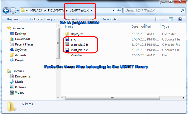
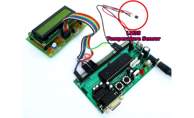
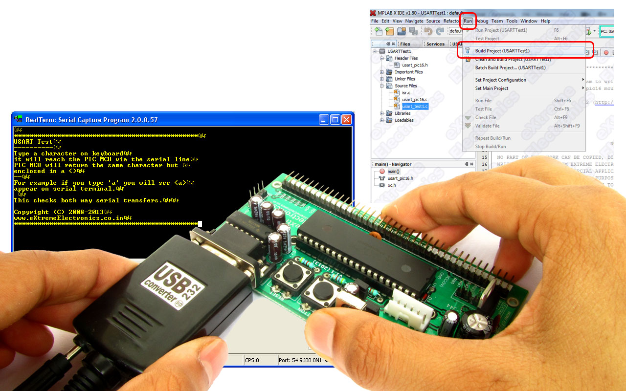
In the last two tutorial we discussed how to make the hardware for serial communication and how to setup a MPLABX Project with support for serial communication functions. Then we complied a demo program to use those serial communication functions and burnt the final hex file to our PIC16F877A development board. Now its time for us to run this demo. Setting up hardware for PIC Serial Communication USART Library for PIC – Setup on MPLAB X IDE To interact with this demo running on your PIC development board. You need a terminal program. A terminal program is a utility tool running on PC that helps you view text data coming from the serial port and also send data to the port. This is handy for initial development of connected hardwares. We use Real Term for this purpose. You can download it from here. Download Real Term. RealTerm The top black area show the character data as they are received by the serial port. The received characters are shown in YELLOW coloured text. The bottom area has lots of tab on it. The Port tab (shown above) is used to configure the serial port. Configure the port exactly as show in the image above. Baud = 9600 Port = <the serial port number where you have connect the PIC development board> […]

USART Library for PIC – Setup on MPLAB X IDE

This article describes the setup and use of the C library for serial communication. We focus on its usage with PIC16F series of MCUs from Microchip. Here we describe how to setup a MPLAB X project with support for serial communication related functions. The library is designed for compilation and use with Microchip’s XC8 C Compiler. Fig. Serial Communication Demo   Creating a New Project in MPLAB X You can create a new project using the MPLAB’s Start page as shown below. Fig. MPLAB X Start Page Alternatively you can use menu File->New Project Fig. Select New Project from File Menu And for those who love the Keyboard over mouse can hit <Ctrl>+<Shift>+<N> Any of the three method will launch the New Project Wizard as shown below. The first step is the selection of project type. From the Categories list select Microchip Embedded and from Projects select Standalone Project. Fig. Project Type Selection Second step is the selection of device for which the project is targeted. Select Mid Range 8-bit MCUs (PIC12/16/MCP) in Family and PIC16F877A in Device. Fig. Device Selection Third step is the selection of debug tool. For that select Simulator. Fig. Tool Selection Microchip MPLAB lets you install more that one compiler. It also lets you install more that one version of the same compiler. So their […]

Serial Communication with PIC16F877A

This article series aims at teaching serial communication between a PIC microcontroller and a PC. We first introduce you with what is serial communication is and how it can used. Then we tell you how to perform serial communication using PIC microcontroller and how we use the USART peripheral for the purpose. We will tell you how our usart library for PIC16F series can be used for easy serial communication, in this part we also discuss how to set up a MPLAB X project for using the USART library. After that we will build a demo project to explore the library. Finally we will burn this demo in a PIC16F877A and establish a serial communication with PC. Serial Communication Their are several serial communication standards like RS232, SPI, I2C etc. Of which RS232 is a asynchronous method. That means it does NOT have a synchronizing clock line. One way data requires only one conductor line. Since it is a two way communication their are two lines between the two device. One for sending data called the Tx and one for receiving data called the Rx. The communication is full duplex, that means data can be sent at the same time data is being received. generally other serial communication like SPI and I2C are used for short range communication like between […]

Making A Thermometer with PIC16F877A

At basic level on microcontroller you can create this interesting project of digital thermometer. It teaches you how to acquire analog data from a sensor and display it on a lcd. We will use a popular MCU PIC16F877A to implement this mini project. The temperature will be read using a LM35 precision sensor. Final result will be shown on a 16×2 alphanumeric lcd module. Fig. PIC16F877A Based Thermometer with LCD   Stuffs Required S. No. Item Image Cost 1 40 PIN PIC Development Board Rs. 769 2 16×2 LCD Board Rs. 296 3 Single PIN Burg Wires Female/Female 20 units Rs. 100 4 12V 1A DC Adapter Rs. 127 5 LM35 Rs. 60     Total Rs. 1,352 Connections The PIC16F877A development board has the PIC16F877A microcontroller chip and its supporting basic circuitry all in a nice high quality PCB. The development board comes fully assembled and tested, thus makes it ideal for doing experiments for learning by beginners. 40 PIN PIC Development Board In the bottom portion of the pic development board you can see a row of male headers. Most of these pins are the microcontrollers general purpose input/output lines and the rest are 5v and GND supply lines. Using these pins you can connect external peripherals (like the LCD board or something else) to do your experiment. […]

LCD Library for PIC – Setup on MPLAB X IDE

This article describes the setup and use of the C library for hd44780 based alphanumeric lcd modules. This library is also available for the AVR family of microcontrollers. This part is focused on its usage with PIC16F series of MCUs from Microchip. Here we describe how to setup a MPLAB X project with support for lcd related functions. The library is designed for compilation and use with Microchip’s XC8 C Compiler. Fig. LCD Demo   Creating a New Project in MPLAB X You can create a new project using the MPLAB’s Start page as shown below. Fig. MPLAB X Start Page Alternatively you can use File->New Project Fig. Select New Project from File Menu And for those who love the Keyboard over mouse can hit <Ctrl>+<Shift>+<N> Any of the three method will launch the New Project Wizard as shown below. The first step is the selection of project type. From the Categories list select Microchip Embedded and from Projects select Standalone Project. Fig. Project Type Selection Second step is the selection of device for which the project is targeted. Select Mid Range 8-bit MCUs (PIC12/16/MCP) in Family and PIC16F877A in Device. Fig. Device Selection Third step is the selection of debug tool. For that select Simulator. Fig. Tool Selection Microchip MPLAB lets you install more that one compiler. It also […]

LCD Module Interface with PIC16F877A

This article describe the hardware setup required for interfacing HD44780 based alphanumeric LCD modules with a PIC16F877A microcontroller. The software part consisting of the LCD library for PIC, its setup and use with MPLAB X IDE and XC8 compiler are described in a separate article. LCD Library for PIC – Setup on MPLAB X IDE A common controller chip used in many alphanumeric LCD module is the HD44780. The purpose of the controller is to generate pixel patterns and drive individual pixels of the LCD to show characters and symbols. In this method the main microcontroller running your application code does NOT need to generate the pixel patterns, it just need to tell the controller chip which character or symbol to show the rest is done by the controller, i.e. the HD44780. The same controller chip is used in many differently sized alphanumeric LCDs. Thus the connection schematic and driving code is same. Pin Details of LCD Module All HD44780 based LCD modules have 16 pin connecters. The detail about these pins is given below. Interface pins of LCD Module   Pin Number Pin Name Pin Type Connected with PIC16F877A’s pin 1 VSS Power Supply – 2 VCC Power Supply – 3 VEE Contrast Adjust – 4 RS Control Line RD4 5 R/W Control Line RD5 6 E Control Line […]