This article describes the setup and use of the C library for serial communication. We focus on its usage with PIC16F series of MCUs from Microchip. Here we describe how to setup a MPLAB X project with support for serial communication related functions. The library is designed for compilation and use with Microchip’s XC8 C Compiler.
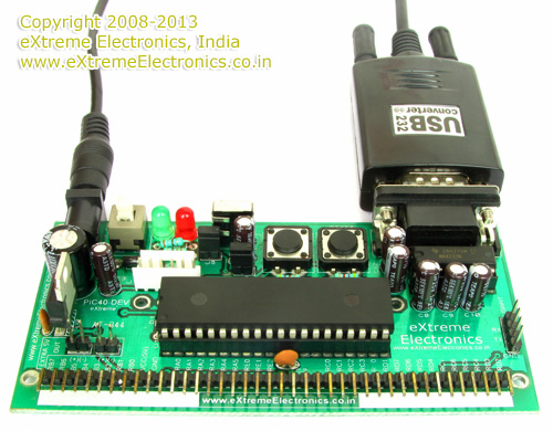 |
Fig. Serial Communication Demo |
Creating a New Project in MPLAB X
You can create a new project using the MPLAB’s Start page as shown below.
 |
Fig. MPLAB X Start Page |
Alternatively you can use menu File->New Project
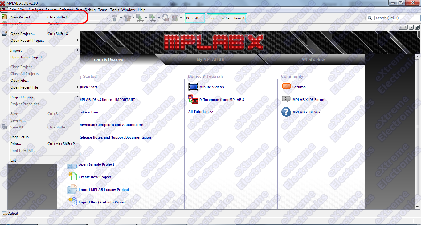 |
Fig. Select New Project from File Menu |
And for those who love the Keyboard over mouse can hit <Ctrl>+<Shift>+<N>
Any of the three method will launch the New Project Wizard as shown below.
The first step is the selection of project type.
From the Categories list select Microchip Embedded and from Projects select Standalone Project.
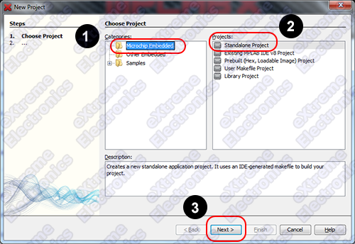 |
Fig. Project Type Selection |
Second step is the selection of device for which the project is targeted. Select Mid Range 8-bit MCUs (PIC12/16/MCP) in Family and PIC16F877A in Device.
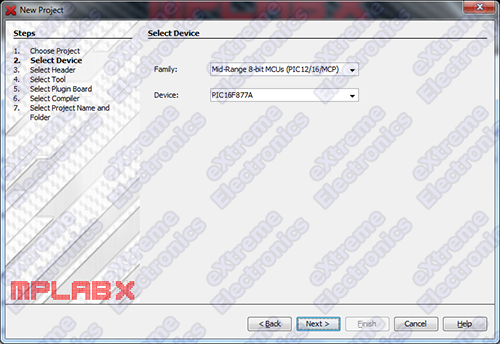 |
Fig. Device Selection |
Third step is the selection of debug tool. For that select Simulator.
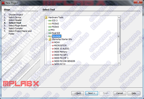 |
Fig. Tool Selection |
Microchip MPLAB lets you install more that one compiler. It also lets you install more that one version of the same compiler. So their is a step to select a compiler for use with your project.
In the image below you can see the compiler XC8 in the list of available compilers, under it is listed all different versions of the XC8 versions available. Since I had only version 1.12, it is the only available option under XC8.
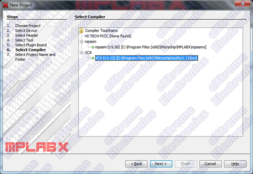 |
Fig. Compiler Selection |
Project name and location
Finally enter the name of project and choose a location on your computer where you wish to save the project and all related files.
For the name you may choose USARTTest1
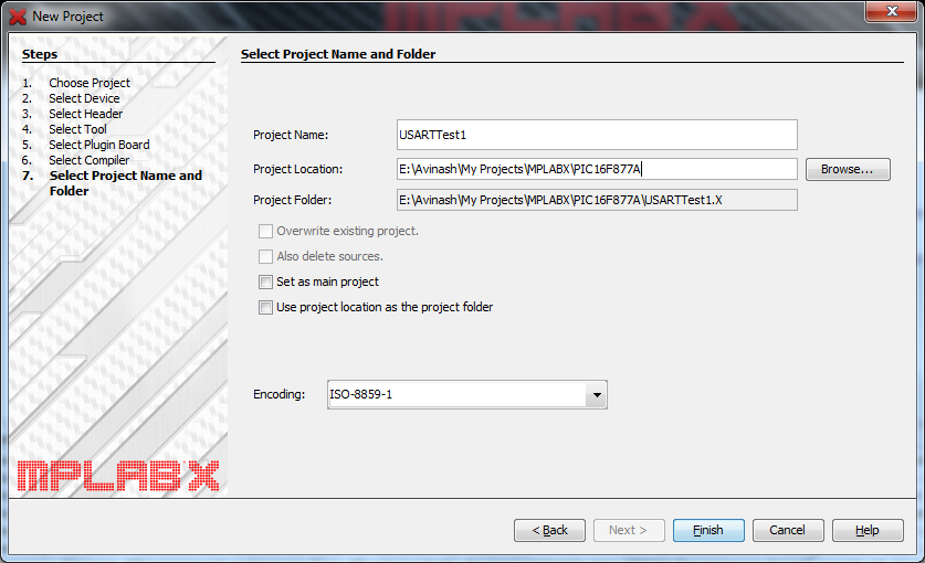 |
Fig. Enter Project Name and Location |
Click Finish.
Configuring the new MPLAB Project
A small configuration that is needed on all MPLAB project is the definition of a global C preprocessor symbol (consider it as a project level global constant). This symbol is named _XTAL_FREQ and it holds a value equal to the frequency at which the PIC MCU will be running. Note the definition of this symbol is very important ! other wise the codes will not be able to generate accurate timing and the code will fail at runtime!
On MPLAB Window, right click over the project’s name in the Project window.
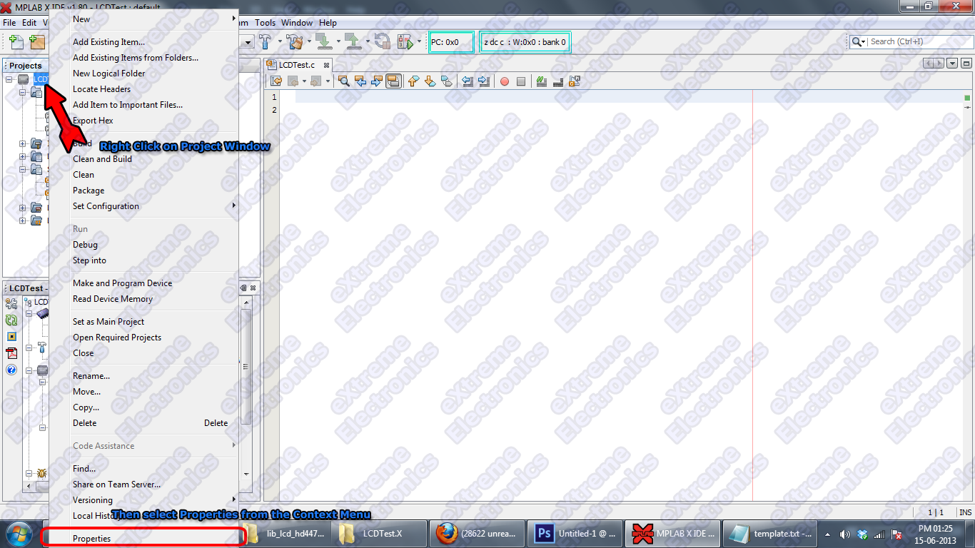 |
Fig. Project Context Menu |
This will bring up a context menu as shown above. From the menu select Properties. It is the last item in the long menu. The Project Properties window will open up as shown below.
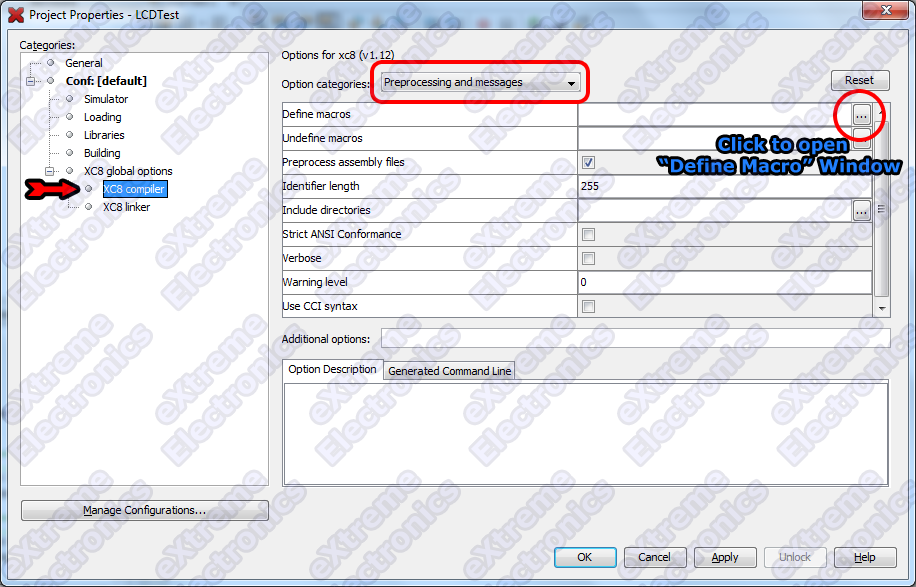 |
Fig. Project Properties. |
In the left hand pane labeled Categories select XC8 Compiler. It will open up options for the compiler which is displayed on the right hand side of the window. In Option Categories select Preprocessing and messages.
And then click on the button as shown in the image above to open up the Define Macro window.
In this window add a macro name _XTAL_FREQ=20000000(two followed by seven zeros, i.e. 20 MHz).
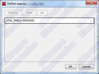 |
Fig. Define Macros. |
Adding USART Library Support Files
The library to drive USART of PIC comes as a set of following files.
- usart_pic16.c
- usart_pic16.h
- isr.c
You can download the package from the link given below.
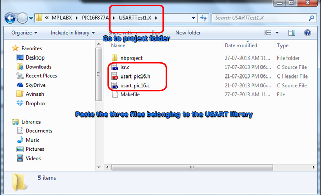
Unzip all the files from the package and then copy them to your MPLAB X (USARTTest1.X in this case) project folder using Windows file manager.
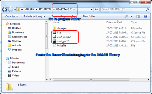 |
Fig. Paste the LCD Lib files to project folder. |
Now when the files have been copied to the project folder. Its time to add the files to the project.
Adding the source files.
Please refer to the image given below to add existing source files in MPLAB X.
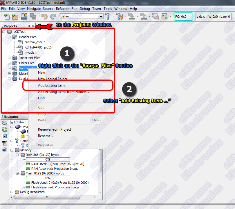 |
Fig. Adding existing source files. |
It will open up the standard file select dialog which lets you select files to add to the project. Select usart_pic16.c and isr.c and it will get added to the project.
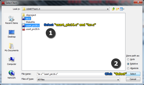 |
Fig. Select usart_pic16.c and isr.c |
Adding the header files.
As you must have seen that the usart library has one header file.
- usart_pic16.h
This header file must be added to the header files section of the project. The steps are same as described above for source files.
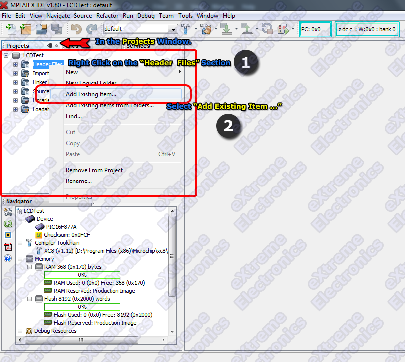 |
Fig. Adding existing header files |
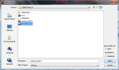 |
Fig. Selecting Serial Communication header files. |
Now the project is ready and has support of using serial communication related functions.
Writing a "Hello World" Application
We will write a small program that will initialize the USART module and write some text to it. The text can be viewed on a terminal program running on PC.
Adding a new source file to project
You will need to add a new source file to the project, this file will hold our main application code. For this
- Right click on the Source Files Section of Project in the Projects window.
- Select New > C Source File …
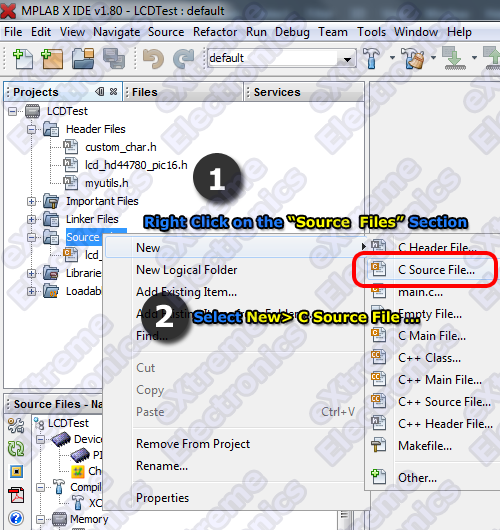 |
Fig. New Source File. |
It will open up the New C Source File Dialog.
In this dialog enter the name for this new file. Enter the name "usart_test1.c" and copy paste the program given below to this file.
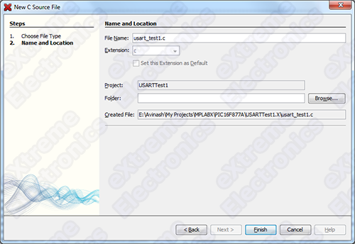 |
Fig. Naming the new file. |
Sample Program
/******************************************************************************

 The most basic example program to write a line of text in to the terminal
 using the USART library for pic16 mcus.

 Compiler: Microchip XC8 v1.12 (http://www.microchip.com/xc)
 IDE: Microchip MPLABX

 MCU: PIC16F877A
 Frequency: 20MHz

                                     NOTICE

NO PART OF THIS WORK CAN BE COPIED, DISTRIBUTED OR PUBLISHED WITHOUT A
WRITTEN PERMISSION FROM EXTREME ELECTRONICS INDIA. THE LIBRARY, NOR ANY PART
OF IT CAN BE USED IN COMMERCIAL APPLICATIONS. IT IS INTENDED TO BE USED FOR
HOBBY, LEARNING AND EDUCATIONAL PURPOSE ONLY. IF YOU WANT TO USE THEM IN
COMMERCIAL APPLICATION PLEASE WRITE TO THE AUTHOR.


WRITTEN BY:
AVINASH GUPTA
me@avinashgupta.com

*******************************************************************************/
#include <xc.h>

#include "usart_pic16.h"

// Configuration Byte
#pragma config FOSC = HS        // Oscillator Selection bits (HS oscillator)
#pragma config WDTE = OFF       // Watchdog Timer Enable bit (WDT disabled)
#pragma config PWRTE = OFF      // Power-up Timer Enable bit (PWRT disabled)
#pragma config BOREN = ON       // Brown-out Reset Enable bit (BOR enabled)
#pragma config LVP = ON         // Low-Voltage (Single-Supply) In-Circuit Serial Programming Enable bit (RB3/PGM pin has PGM function; low-voltage programming enabled)
#pragma config CPD = OFF        // Data EEPROM Memory Code Protection bit (Data EEPROM code protection off)
#pragma config WRT = OFF        // Flash Program Memory Write Enable bits (Write protection off; all program memory may be written to by EECON control)
#pragma config CP = OFF         // Flash Program Memory Code Protection bit (Code protection off)

void main()
{
  //Initialize USART with baud rate 9600
  USARTInit(9600);

  //Write intro text
  USARTWriteLine("***********************************************");
  USARTWriteLine("USART Test");
  USARTWriteLine("----------");
  USARTWriteLine("Type a character on keyboard");
  USARTWriteLine("it will reach the PIC MCU via the serial line");
  USARTWriteLine("PIC MCU will return the same character but ");
  USARTWriteLine("enclosed in a <>");
  USARTWriteLine("--");
  USARTWriteLine("For example if you type 'a' you will see <a>");
  USARTWriteLine("appear on serial terminal.");
  USARTWriteLine(" ");
  USARTWriteLine("This checks both way serial transfers.");
  USARTWriteLine("");
  USARTWriteLine("Copyright (C) 2008-2013");
  USARTWriteLine("www.eXtremeElectronics.co.in");
  USARTWriteLine("***********************************************");
  USARTGotoNewLine();
  USARTGotoNewLine();

  while(1)
  {
      //Get the amount of data waiting in USART queue
      uint8_t n= USARTDataAvailable();

      //If we have some data
      if(n!=0)
      {
          //Read it
          char data=USARTReadData();

          //And send back
          USARTWriteChar('<');
          USARTWriteChar(data);
          USARTWriteChar('>');
      }

  }
}
Now its time to build this project. Building is the process of compiling all files in the project and then linking them to build the final executable image. This executable image is in the form of a hex file. The name of this file is <project name>.X.production.hex
To build the project select Build Project from the Run Menu.
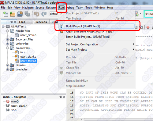 |
Fig. Building the project |
If you have did everything precisely as described in this tutorial your project should build without any problem and you should get a BUILD SUCCESSFUL message in the output window of the MPLAB X IDE.
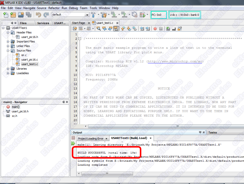 |
Fig. Build Success |
The hex file which is actually the executable program in machine language, is generated in the folder "\dist\default\production" which is in your project folder.
The name of the file should be USARTTest1.X.production.hex
Burning the hex file to MCU
Burning is the process of transferring the data contained in this hex file to appropriate memory locations on the chip so that chip can execute this program. To burn a chip you need a device programmer. A device programmer consists of a hardware and a driving software. You can purchase a device programmer for PIC16F MCUs from our online store. Please note that we ship through out India and to many other countries. International customers can pay safety using Paypal while Indian customer can use Credit Card, Debit Card or Online Banking for purchase.
How to burn the hex file to PIC MCU using this programmer is described in this article.
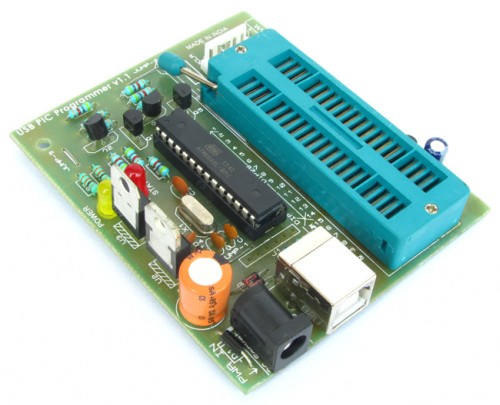 |
Fig. USB Port Based PIC Programmer |
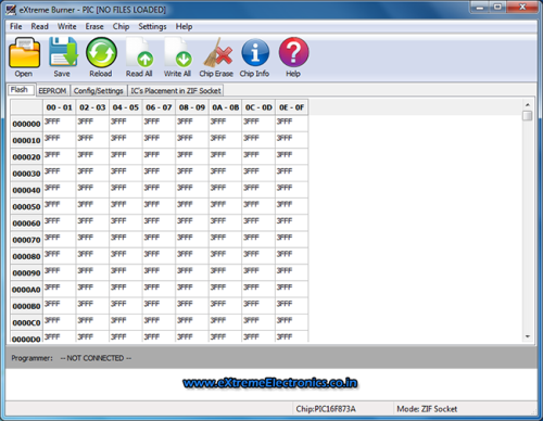 |
Fig. Software Interface |
Hardware
Hardware required to run this demo is described separately in this article.
Steps to Run this demo is also described in a separate part.
|
Fig. Serial Communication Demo |
Downloads
- Complete MPLAB X Project for Basic USART Demo.
- HEX File Ready to burn for Basic USART Demo.
- USART library.
By Avinash Gupta
www.avinashgupta.com
Facing problem with your embedded, electronics or robotics project? We are here to help!
Post a help request.
Avinash
Avinash Gupta is solely focused on free and high quality tutorial to make learning embedded system fun !
Follow Me:


Pingback: Serial Communication with PIC16F877AeXtreme Electronics
Pingback: PIC16F877A Serial Communication Demo |eXtreme Electronics