What is a timer ?
A timer in simplest term is a register. Timers generally have a resolution of 8 or 16 Bits. So a 8 bit timer is 8Bits wide so capable of holding value withing 0-255. But this register has a magical property ! Its value increases/decreases automatically at a predefined rate (supplied by user). This is the timer clock. And this operation does not need CPU’s intervention.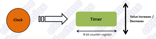 |
Fig.: Basic Operation Of a Timer. |
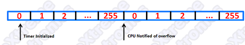 |
Fig.: Basic Operation Of a Timer. |
Using The 8 BIT Timer (TIMER0)
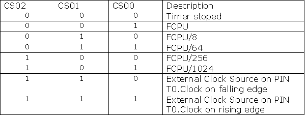
The ATmega16 and ATmega32 has three different timers of which the simplest is TIMER0. Its resolution is 8 BIT i.e. it can count from 0 to 255. Note: Please read the “Internal Peripherals of AVRs” to have the basic knowledge of techniques used for using the OnChip peripherals(Like timer !) The Prescaler The Prescaler is a mechanism for generating clock for timer by the CPU clock. As you know that CPU has a clock source such as a external crystal of internal oscillator. Normally these have the frequency like 1 MHz,8 MHz, 12 MHz or 16MHz(MAX). The Prescaler is used to divide this clock frequency and produce a clock for TIMER. The Prescaler can be used to get the following clock for timer. No Clock (Timer Stop). No Prescaling (Clock = FCPU) FCPU/8 FCPU/64 FCPU/256 FCPU/1024 Timer can also be externally clocked but I am leaving it for now for simplicity.TIMER0 Registers.
As you may be knowing from the article “Internal Peripherals of AVRs” every peripheral is connected with CPU from a set of registers used to communicate with it. The registers of TIMERs are given below.
TCCR0 – Timer Counter Control Register. This will be used to configure the timer.
Fig.: TCCR0 – Timer Counter Control Register 0 |
As you can see there are 8 Bits in this register each used for certain purpose.
For this tutorial I will only focus on the last three bits CS02 CS01 CS00 They
are the CLOCK SELECT bits. They are used to set up the Prescaler for timer.
TCNT0 – Timer Counter 0
Timer Interrup Mask Register TIMSK
This register is used to activate/deactivate interrupts related with timers. This register controls the interrupts of all the three timers. The last two bits (BIT 1 and BIT 0) Controls the interrupts of TIMER0. TIMER0 has two interrupts but in this article I will tell you only about one(second one for next tutorial). TOIE0 : This bit when set to “1” enables the OVERFLOW interrupt. Now time for some practical codes !!! We will set up timer to at a Prescaler of 1024 and our FCPU is 16MHz. We will increment a variable “count” at every interrupt(OVERFLOW) if count reaches 61 we will toggle PORTC0 which is connected to LED and reset “count= 0”. Clock input of TIMER0 = 16MHz/1024 = 15625 Hz Frequency of Overflow = 15625 /256 = 61.0352 Hz if we increment a variable “count” every Overflow when “count reach 61” approx one second has elapse.
Setting Up the TIMER0
  // Prescaler = FCPU/1024
   TCCR0|=(1<<CS02)|(1<<CS00);
 //Enable Overflow Interrupt Enable
   TIMSK|=(1<<TOIE0);
 //Initialize Counter
   TCNT0=0;
Now the timer is set and firing Overflow interrupts at 61.0352 Hz
The ISR
ISR(TIMER0_OVF_vect)
{
//This is the interrupt service routine for TIMER0 OVERFLOW Interrupt.
//CPU automatically call this when TIMER0 overflows.

//Increment our variable

   count++;
   if(count==61)
   {
   PORTC=~PORTC; //Invert the Value of PORTC
   count=0;
   }
}
Demo Program (AVR GCC)
Blink LED @ 0.5 Hz on PORTC[3,2,1,0]
#include <avr/io.h>
#include <avr/interrupt.h>

volatile uint8_t count;

void main()
{
   // Prescaler = FCPU/1024
   TCCR0|=(1<<CS02)|(1<<CS00);

   //Enable Overflow Interrupt Enable
   TIMSK|=(1<<TOIE0);

   //Initialize Counter
   TCNT0=0;

   //Initialize our varriable
   count=0;

   //Port C[3,2,1,0] as out put
   DDRC|=0x0F;

   //Enable Global Interrupts
   sei();

   //Infinite loop
   while(1);
}

ISR(TIMER0_OVF_vect)
{
   //This is the interrupt service routine for TIMER0 OVERFLOW Interrupt.
   //CPU automatically call this when TIMER0 overflows.

   //Increment our variable
   count++;
   if(count==61)
   {
      PORTC=~PORTC; //Invert the Value of PORTC
      count=0;
   }
}
Downloads
Hardware
ATmega8A running @ 16MHz. Connect LEDs using 330ohms resistors on PB1. Thats it for now meet in next tutorial. And please don’t forget to post a comment, I am waiting for them !
Move On …
Download PDF version | Get Adobe Reader Free !!!
Pingback: Timers in Compare Mode - Part I | eXtreme Electronics
can you send me a program to make a reaction tester please
@Van de Poel Dominic
I don’t understand by “reaction tester” pls give details!
Pingback: PWM Signal Generation by Using AVR Timers. | eXtreme Electronics
When you write example code you should not use shortcuts. Shortcuts allow advanced programmers to code faster, but make it extremely difficult for beginning programmers to follow.
Consider:
x++; vs. x = x + 1;
A beginner might not know what ++ does, and even if they do, x = x + 1 is still more clear and easier to follow.
Now consider:
TCCR0|=(1<<CS02)|(CS01);
I know you are performing a bitwise operation on the timer counter control register. I know from your commenting the code that you are setting the prescaler to FCPU/1024. I know from the chart that means you are setting the last 3 bits to 1 0 1. Yet I have no idea what that line of code is doing. So if I wanted to set the clock prescaler to /512 I have no idea the change that would be needed.
I’ve studied it and concluded that it appears this might do the same thing:
// set prescaler to FCPU/1024 by setting last 3 bits of TCCR0 to 101
TCCR0 = TCCR0 & 0b11111101 // turn off bit 1
TCCR0 = TCCR0 | 0b00000101 // turn on bits 0 and 2
yes he is correct!
MtAVRest, possible somewhere you’re right. But..
1. Please agree that a real noob will not start it’s programmers career from firmware programming. Even if AVR’s are easiest.
2. C++ is not Basic. I don’t see any reason to rewrite this code: x++. It is not obfuscated. It is syntax. And really simple one. Even more, there is a clear comment in the code:
//Increment our variable
count++;
3. Now consider this:
TCCR0|=(1<<CS02)|(CS01);
And this:
TCCR0 = TCCR0 & 0b11111101;
TCCR0 = TCCR0 | 0b00000101;
What are simpler to read? It is impossible to understand your code without looking at register documentation. First example, at least, have the register bit names.
IMHO, author is good, but your comment is simply ignored.
P.S. My blog is not such descriptive, but what the heck 🙂 :
http://blog.stranadurakov.com/2009/04/01/set-up-avr-timer-interrupt/
Hello Andrejs,
🙂
Nice and Correct response to MtAVRest!
I thank you for time and effort to answer his doubts precisely.
Thank you again 🙂
when i started working with timers I also wasnt sure what TCCR0|=(1<<CS02)|(CS01); meant, but I knew it had to do with setting the CS1 and CS2 bits.
I looked it up andhave been using it since. That is how one learns.
One could havesimilar criticism saying 'in a tutorial you shldnot use this at all, but just use a library' which ofcourse is nonsense.
As long as a tutorial is well written it doesnt matter if there is a piece of difficult code in it. as long as you know what it is doing you can find out how it is doing that and honestly that is how omne learns better, rather than just reading over it, dive in it.
i couldn’t understand how have you obtained 0.5 Hz in the last code?
@pankaj
interrupts occur at around 61 Hz so in 1 sec there are 61 interrupts.therefore counter is set to 0 every 1 sec.that means portc is toggled every 1 sec.that means it is on for 1 sec and off for 1 sec.so time period is 2 sec and freq is 1/2=0.5Hz
@Nischey Grover
Very Nice work to help out Pankaj. 🙂
Pingback: AVR Project - Digital Stop Watch with ATmega8 | eXtreme Electronics
Hi, this is propably quite stupid question but i’ve been figuring it out several hours now with no luck.
i’m getting this error: ‘TCCR0’ undeclared (first use in this function)
So my compiler thinks TCCR0 is a variable that havent been introduced but it’s a register. right?
how do i tell it to my compiler?
I’m using AVR studio 4 as my compiler.
@Kalle,
TCCR0 is a register associated with TIMER0. It will only be available in chips which has Timer 0. If you try to compile when a chip which does not has a specific peripheral (like TIMER0 in this case) you will get the above error. So please try to select appropriate chip like ATmega8 or ATmega16 from the configuration dialog of AVR Studio.
AVR Studio usages is given here
https://extremeelectronics.co.in/avr-tutorials/part-iv-the-hello-world-project/
Kaile, first thing you need to tell us is what chip you are using, because there is some differences between some avr versions.
For example, TCCR0 should be TCCR0A in ATmega164P/324P/644P.
It works now, had to rename TCCR0 to TCCR0A for my chip. Thanks for fast replies.
No problem, glad this helped. 😉
Hi, i am not getting clear idea about this statement
TCCR0|=(1<<CS02)|(CS01);
I understood the logic that this command sets the TIMER0 to 00000101 by bitwise operation (for prescaler to be FCPU/1024), but how this is happening, please elaborate.
I understood other two syntaxs-
TCCR0 = TCCR0 & 0b11111101;
TCCR0 = TCCR0 | 0b00000101;
@Aditya Sharma
Hey man see this
https://extremeelectronics.co.in/avr-tutorials/programming-in-c-tips-for-embedded-development/
volatile uint8_t count;
‘volatile’ I have not heard about this datatype, what this is for?
First of all volatile is NOT a data type. It is used to mark a varriable as volatile (what is this? Please read on).
Suppose we write
while(1)

{

 	if(a==250)

	{

		print("Done")

 		break;

	}

	else

	{

		z++;

	}

}
When the compiler compiles the above code it tries to optimize the code. It sees that a is not modified any where in the loop, so instead of getting the value of ‘a’ from memory to register in each loop it just gets the value into register ONLY one time. It does same with all varriables which are not modified in the NORMAL course of loop execution. But what if the value of ‘a’ is modified by an ISR (interrupt service routine) !!! Interrupt can occur at any time thus breaking the normal course of execution and executing the ISR (which say increments ‘a’) and then silently continues execution from where it left.
This kind of varriable that can be updated by Hardware are called volatile varriables. A very common example is PORT input PINs their value can be changed by the external environment (like presssing a button). Other varriables that are controlled 100 % by the software are simple varriables
Got it ???
All varriable that are shared between ISR and main program MUST be “volatile”
Thanks for this really helpful explanation, the ‘volatile’ concept is clear to me now.
Regarding bitwise operations i have understood the tutorial well before asking you the query. The problem was that earlier the statement was
TCCR0|=(1<<CS02)|(CS01);
and now you have changed it to..
TCCR0|=(1<<CS02)|(1<<CS00);
This one is of-course right, but the former one was wrong as i suppose so i pointed out.
Thanks again;
Aditya Sharma
Also, can you please answer the query posted by one of the user on this link…
http://robozeal.blogspot.com/2009/03/basic-mechanisms.html
he is having some doubts in Atmega8 programmer and some more stuff, i have not used Atmega8 and USB programmer so unable to clarify his doubt, Please do have a look if you don’t mine!
which timer should i use to simulate a set of traffic lights? any idea on how i could implemnent in?
Yuveer,
Due to high delay you need to use 16-bit timer. You can use timer output from one side and 3 PIO outputs from other side to build simple traffic light matrix.
In software, you just build interrupt which will analyze when and what to switch on or off depending on the global variables you set.
Hope this will help.
HI,
i am new to this AVR controllers. If frequency of Overflow = 61.03Hz & when “count reach 61” approx one second has elapse.
How did you calsulate one second elapse? Can’t it be 1ms?
I dont understand this. Can you please help me?
@abcd
Pls don’t flood with silly comments !!!!!!!!!!!!!!!!
If you don’t know relation between time and frequency pls go for some other profession.
🙁
It may help for some other (because everyone don’t have basic foundation due to many reasons )
For this you need to understand mainly two things
1)Understand about frequency (cycles/ second).
2)timer operation in micro controller.
1)frequency is nothing but number of clock cycles per second.In this example 15625Hz so
15625 clock cycles or counts / second, that’s it.
2)In digital electronics timer is a counter
it’s basic application is calculate time.
say suppose timer is running at 15625Hz
means 15625 counts/second ,timer’s have counting registers to hold this counts.
For a 8 bit timer, counter capability is
0 to 255 (because it is 8 bit (2^8)).
so our 8 bit counter not capable for store
those 15625 counts that’s why overflow
concept came to the picture 8 bit counter will repeat it for reach 15625 counts that is @ 61 times we need to repeat for to reach 15625 counts (1 completee cycle).So as frequency definition stands that after counting 15625 counts that time is 1 seconds, That’s why for every 61 ISR counts 1 second time is elapsed,
i hope you understand.
YEP SIR WE UNDERSTAND ACCURATELY AND VERY PRICISELY U CLEARED MY PROB THANKS FR DAT
@abcd,
Check Nischey Grover comment on this page dated June 18th, 2009 at 4:40 pm, it will explain you how this code is working.
I highly appreciate 🙂 Mr Andrejs work of Finding and giving a solution to “abcd”.
-Admin
Hello Avinash,
I read your AVR timer Introduction tutorial. For every 1 sec here timer 61 overflow interupts. Can you please explain me how to Initialize a timer to generate a overflow interrupt for every 15ms?
Hi, what blog platform is this? Is it working for you or..? I would really like it if you could answer this question! Regards!
@Verda
This is WordPress !!!
i found it quite helpful for me ….it helped me clear my concepts and hope more n more such tutorials ..thanx a lot
Frequency of Overflow = 15625 /256 = 61.0352 Hz
Can some explain to me the logic behind dividing the Clockfrequency by 256.
@Jay
Didn’t you read 2nd Paragraph? Timer Overflow?
I get angry when I see questions like this.
When you not get anything you should try to read again.
@Jay
Why would anyone explain you the same thing that is written above?
Can’t you get simple arithmetic ???
@Jay
same question throws in my head … but like Avinash said, you have to read again to understand.
(Answer: because the TIMER0 is 8-bit wide so it can count 2^8=256 clocks, but only one time it generate an overflow in those 256 clocks)
@Avinash
Keep up the good work … you are amazing !!!
I find your comments very helpful to me.Now I have a question
if I need multiple time-delay of various times,what to do ?I mean there is just only one 16 bit timer-counter,how to use it for all that time-delay?Please help me.
Sayantan,
Depending on the chip there may be few timers that you could use (megaAVR has max 4 of them). If you need to get one more timer you probably have two options:
1. Move to a chip with higher 16-bit timer count
2. Try to optimize your code so it will share your timer with another code.
I have got some problem dealing with the timer0 and timer2 which are used to control the steps of two stepper motors on my robot. In order to use PID controller I will need the motors to change the speed according to the output of the controller. If I were to use the OCR0 and OCR2 (reducing/increasing) to change the speed of the motors, how would i know what is the speed the motors are going??for example i want the motors to move forward at 12.56cm/sec. I will have to enable the interrupt to increase the steps of the motors but how would i know what speed are they going at???
do u have any examples that i can look into for controlling two stepper motors at different speeds based on the situation it is in by using the interrupts. I have seen the examples of one stepper motor using timer0 but it was not very helpful because the steps of the motors are predefined and that is not the case in my project.
Pingback: time interrupt activated button avr « Msmihai's Blog
Pingback: Servo Motor Control by Using AVR ATmega32 Microcontroller | eXtreme Electronics
niece contents ……………….helpful 4 all beginners…niece approach with eg.
avinash good work
Awesome tutorials….I have gone through most of them…and they are so simple and elegant….I will be forever grateful to you..:) Do keep up the good work.
hi avinash,
i ported ucos to atmega16 but OSTimeDly is not functioning.can u help me pls…
i have seen the disassembly for the OSTickisr in asm file the timeroverflow0 interrupt vector is not placed at 0x0012
Pingback: Interfacing Ultrasonic Rangefinder with AVR MCUs | eXtreme Electronics
Many thanks for the crystal clear article. This really helped me get started.
Pingback: Open-collector interface
Pingback: Daily Summary February 8th « Tim Cinel
many thanks for the simple and clear tutorial
best regards
Hi!
great site and informative and comprehensive tutorials.
You’re talented programmer. I would appreciate more examples helping us to broden understanding of using the timers counters interrupts adc ..etc and broden our c programming techniques.
Wish you all the best.
I 100% agree with MtAVRest comments about shortcuts.
I didnt really understand first what below line does.
TCCR0|=(1<<CS02)|(1<<CS00);
Looks like shift bit to left..
But thanks for your tutorial. very helpful!
@JonS
You don’t get the line ?
TCCR0|=(1<<CS02)|(1<<CS00);This is a very basic technique of embedded programming. Found in most of my and others avr-gcc programs.
It is like saying I have read and liked the “Harry Potter” novel but just cant got the symbol ‘A’
Hey you need to learn the alphabets before you read a novel!
The mistake you are doing are
>> Not reading the avr-gcc’s manual (the compiler you are using)
>> Not having enough knowledge of the C language itself.(the language you are using)
Anyway.
The above line means
Set the bit named CS02 and CS00 to ‘1’ in the register named TCCR0
How it is done?
Well read the bit operator like
BITWISE OR
BIT SHIFT Operators of C
Other wise read this tutorial
https://extremeelectronics.co.in/avr-tutorials/programming-in-c-tips-for-embedded-development/
I like your tutorial, i see much comments about bit wise and shortcuts, for beginiers like me seeing the shorcuts it make it easy to understand the code, but not having it, it help me to learn new things, bottom lne I’m pro the use of shortcuts
whoever don’t like them it’s because he must code on assmbler.
Thanks for your sharing. The explanation is simple and easy to understand.Keep it up!HEHE
@Av
Hey Av.. had to go away for a spell. You’re still the best by a long shot! Number 1. Keep up the good work.
@W Lewis
Thanks !!!
From
Av
Pingback: Multiplexed Seven Segment Displays. | eXtreme Electronics
fantastic tutorial ..i was confused bt after reading this i will be alble to use timer0
thanks
very good tutorial.
now iam able to understand the use of timer. i want to measure the duration between two pulse(0 to 4000 microsecond)i.e to measure the delay time to blast a fuse unit of missile. there is already a old delay timer machine to measure this but it is not working now.my plan is to trigger timer0 when first pulse come and to stop timer0 when second pulse come and thereafter to take readout tcnt0 plus no of overflow occur multiplied with 255. here my incriment is 1 micro second. pl suggest will it give accurate time.
hmmmm ….
im a newbie tooo ….. i got the hang of the thing timers…..initially i was confused at TCCR0|=(1<<CS02)|(1<<CS00); ….. not because of the operator but the operands … i assumed that the variables CS00, CS01 and CS02 are predefined in avr/io.h or avr/interrupt.h …. one more thing….. u have used an or operator before the equal to symbol … i understood that too but what i want to know is will it make a differnce if u didnt use the operatoer …the operator there is just to ensure that the other bits are not altered right ?
Pingback: Composición Algorítmica | Palmera blog
@avinash : man nice job …really really helpful tutorials. Try not to be harsh at newbies, this will flee them away !!
@Shayan,
I am not harsh at newbies. I am harsh on those who don’t have correct “approach to solve problems” or those you cannot be helped.
Pingback: AVR controller timer basics
Hello ! I want to ask you that do we have to initialise the counter again in the ISR Routine for the timer to be reloaded or does it loads itself for the whole program when it is initialised in main program ??
For example, if i want to run a program in ISR every 100ms ..then what should i do?? Please guide me…
i want to do this
int main(){
…count initialise;
while(1);}
ISR(routine){
//repeat the below program after every 100ms
….}
wow nice explain, i can understand more than before. thank you very much..
You do not need to mark a global variable volatile, am I wrong?
I liked the way you explained the timer so much.
Kind Regards,
Mahmoud
Pingback: atmega168 not working
wil u plz tell me what do u mean by volatile variable and when v declare it
No I will NOT because it is already explained in every book on C! And it is assumed that an embedded developer knows C well. Or atleast has 3 or 4 book on C on his/her book self.
Bye.
With embedded programming the variables which are used/altered by the interrupt routines need to be declared as global volatiles.
I usually stick them just after my #defines and before my functions. Because they are defined outside of any functions, even main(), enables the variable to be accessed by all the functions in the program.
The variable is declared as volatile to stop the complier assuming the variable is a constant.
This drove me nuts when I was just learning
Pingback: [SOLVED] ATTiny13 get current time
sir,
i want 2 control speed of bldc motor by pwm using atmega8.i want 2 vary speed from 1ms to 2ms.eg at 1ms,1.25ms,1.50,1.75ms,2ms at 50hz.will u plz tell me abt how 2 code in c.how prescaler should set or mail me code in c for 1ms at 50hz.
thank you
Really amazing sir,
I have some doubt about PWM
How can I contact you sir?
My mail-aji_maxim@yahoo.in
@Ajit Kumar,
so what you have done with the above comment? Funny.
Thanks
Pingback: Using Delay Routines in AVRStudio
Pingback: AVR microcontroller(atmega16)
Hi Avinash. I like all your tutorials. I have some questions.
1st. I port your code to ATMega8,but now I can detect is button presed on ports. Why??
2nd. You said that about second type of interrupt of Timer0 you will tell in next tut, but next tut is about timer1.
3rd. Why you stopped writing articles??
Thnx.And sorry for silly questions I’m new in uC’s.
@Garegin!
3rd. Why you stopped writing articles??
Ha ha !
Will write now, may be from next month.
And please Avinash write an article about TWI(I2C). I need to understand it , but all articles in i-net are pieces of shit.
Thanks. I’m waiting for your articles, because now is next month.
THANKS.Really helped me a lot.I was having trouble to understand interrupts ,not anymore “yay”.after this I used TIMER1 and OCR1A(for PWM) also TIMER2…it’s fun AVR interrupts .
you’re great! thanks for all the informations inside your site!!
very good explanation 🙂
Thank you
Thanks.I find my question.
the a above comments are getting printed incorrectly no idea know why??
my actual code is :
int main()
{
DDRB |= 0b00000001;
PORTB |= 0b00000000;
TCCR0|=(1<<CS02)|(1< 254)
{
count++;
if(count == 61)
{
count = 0;
PORTB ^= (1 << PINB0);
}
}
}
}
but i m not getting my led blinking as expected.
done same thing with interrupt i m getting the proper output
As ,i am new in embedded c so plz help me as :i want to generate 1 mhz waveform in pwm in atmega32,how i can code in c.
What is TOIE0 ? There is no description of it and tutorial goes very fast !
awesome work here!!
hi!..i wanted to display the count value on an lcd after the timer has been started and stopped whenever the i/p makes a high to low transition…can i do it by jus passing the value of tcnt reg as a char to the lcd??..i dunno wer the exact count value will be stored and if it can be acccessed directly and given to an o/p port…
@Vrinda,
When ever you are trying to do anything in any field, first you need to know the basic very well! Thorough understanding of basic is very much important. I hate to see people with confused idea?
Do you know anything about character representation in computers and ASCII code?
yea i do know about ascii code..atleast i did try converting the timer value to ascii and then transferred it to the o/p port which is inturn connected to the lcd…..sorry about not putting the question properly…i wanted a sequential display rather than the final value of the timer
Dear sir i am repairing a watch so that for after every 60 seconds i have to generate a waveform that will further drive my watch’s minute’s niddle…i have generated a delay of 60 seconds but using the same timer i am unable to generate a waveform for only 250 ms…because i have used 4Mhz clock with 64 as prescale…so my timer clock is reduced as 15625 Khz…for 1 sec i will have to put 15624 in TCNT1…i run a loop at 60 times then i wll get 60 seconds delay but for 250 ms its value goes out of range as 16 bit timer registers max limit(65536)…so what should i do?
can u plz help me my dear…..
@lokesh tiwari
Sorry a yr. too late..! yet it may be of use to others….
U can use the 16 bit Timer1, & if u use an AtMega8 chip, with default internal oscillator of 1 MHz, & then set the prescaler as divide by 1024, & U should get an elapsed time of approx. 60 seconds at every ‘Overflow’….bcoz,..Timer1 counter which OverFlows after it counts up to 65,535, so for each overflow, about 60 sec. has passed. In practice I got a time of about 67 seconds.. & I defined a variable ‘count’, & then count++, so that when if(count==4) , about 4.5 minutes have elapsed….(I needed that long a time..to run my washing machine ‘wash motor’ ON for wash, & then OFF for same time for ‘soak time’ for the clothes…), – as my ‘videocon’ washing machine’s original control board is now faulty, & is no longer available, so I’m trying to develop my own, – but I hv only this wash part as semi-automatic, & the complete automatic control I could not develop,…can someone help me in this regard???
nice work.I need ur help. I want to reset and restart digital watch using a same switch as I want to display digital watch.Here is my code:
if(!(PINB & (1<<PB4)))
{
TCCR1B=(1<<WGM12)|(1<<CS11)|(1<<CS10);
}
else
{
clock_millisecond=0;
second=0;
minute=0;
hour=0;
TCCR1B=(1<<WGM12)|(1<<CS11)|(1<<CS10);
}
Here in if condition first clock is incrementing its value but in else statement the clock is set to 0 and second clock is not incrementing its value.Please help i want to increment both clock after resetting it to 0 using a single switch.Plz help
Hello,
I have seen your posts and learned a lot from it. U have great going on here. I would like to congratulate you first. 🙂
I am sort new to AVR. i am using atmega32.. I have used a simple for loop for time delay:
void delay(void)
{
long i;
for(i=0; i<65000; i++);
}
Here i am switching 4leds on port c.. the problem is, after running the program, all LEDs are glowing. 4 LEDs are dark and the other 4 tht were supposed to turn on after the delay are also glowing but with less intensity.
wht might be the problem? i have tried many thing with it, bt it isnt working.
thankz.. 🙂
you are so graceful in this presentation.provided almost what i need.. thank you..
how to check ISR body .i did use “step into” but its not showing execution of ISR
What if you want a precise low frequency clock from a 8 bit timer? Say 1Hz.
first of all..thank you for great and nice explaination. by using avr,i want to achieve 50hz frequency using pwm…IS IT POSSIBLE???
@Tarun,
If it is possible to land man on moon than why would generating 50KHz would be IMPOSSIBLE?
Hey dude @Avinash can i know aboout the global interrupts and the function sei() in the program.
Hello Sir
I want to start programming with AVRGCC (WINAVR).
Please help me to start the project in it.
Please Also make clear how to use programmers notepad, make file etc.
thanks & Regards
Bipul kumar
How to use a crystal oscillator as external clock source?
Buddy I dont know who r u! But really appreciate for your work. I am from Automotive backgr. Electronics stuffs are totally new for me. doing masters here in Germany. I found ur page nd its really useful for beginners. Again Thank you! Danke schoen 🙂
@Harsh Patel, Thank you. I am glad you found them usefull.
i want to ask that i want to give digital i/p by a infrared sensor to atmega32 and want to count the no of objects passing through the sensor what code should i use to increment the counter
Hello sir
i need verilog (HDL) code for this program.
I would be appreciate if you could help me.
Hi… i was following your tutorials and it was very use full.. sorry for asking this question here but i wanted to know how to trigger multiple interrupts at different different occasions. I was now able to find a tutorial on that form you… It would be great if you can guide me through this because you tutorials are simple and easy to understand.. thank you..
Hi Avinash – excellent set of tutorials. Many thanks in making this funda available
to us non engineers
i need help in bascom code trigger count at specific number or event capture start
somthing how i need simple example to understand.
and speed rpm in bascom example please
please find my enqirey
iam asking about bascom counter timer config timer0=counter,edge=rising
do loop until counter>=70
portb=&b00000001
wait 2
portb=&b00000000
portb=&b00000010
wait 2
portb=&b00000000
loop
Ineed to get event in specific number without counter stop or reset it how
iam adil
Hi. I need a c program for TCS3200 Sensor which recognize RGB. Thanks alot.
how to Display the Counter on the LCD then ?
Thanks bhai..!! 🙂
What prescalor should i take to blink my LED at every 0.5 sec i.e. 2Hz??
Really useful tutorial…awesome..learned some stuff..thanks lot..great job..kudos!
how can i run this code at atmega32 i didn’t find any thing point to this in the code but when simulating in protus . the code run only at atmega8
soory i discovered that this code is built to fit atmega8 in atmel studio i copied the same but build for atmega32 and this run 🙂
its wonderful tutorial , it really help me in my Degree course i am fan of urs.
Pingback: Penggunaan kursor untuk praktik Triac
Pingback: Praktik dasar PWM dengan Arduino – ELDA