In the last chapter we learned about the development process of embedded systems. We saw what hardware and software tools are required to work with Atmel AVR microcontrollers. We learned about programming languages, compilers and IDEs. In this chapter we will go in the step by step details of using the Atmel Studio IDE to enter and compile a program written in C language. We won ‘t be going in the details of the program. That means what each line means and does. We will simply copy/paste a program as our intention in this chapter is to get familiar with the IDE only. Program will be discussed in latter chapters.
You can start Atmel Studio 6 by using its icon from the Windows® Desktop or the Start Menu.
Atmel Studio 6 Startup Screen
The First screen shown up after the AS5 has started is the Start Page. The start page helps you quickly create a new project or load your previous project without wasting much time.
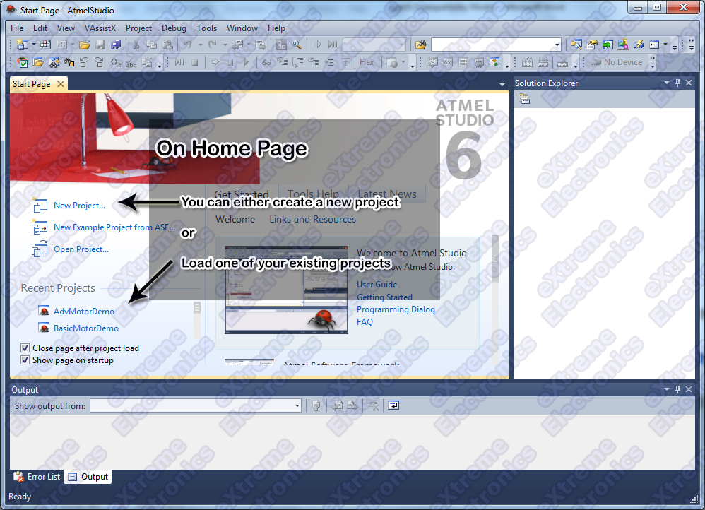
Atmel Studio 6 Home Screen
To create a new project we select New Project … option from the Start Page.
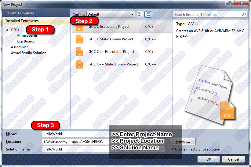
AS6 will show you the New Project Wizard as shown in the above image. From the project template area (Installed Templates) select C/C++ as the project template. From the project type area select “C Executable Project” . After that fill out the project details at the bottom like project name, its location on your PC etc. Finally Hit OK.
Name the project: led_blink
Next to the project detail window comes the Device Selection Window. That lets you choose the target MCU for your project. For our very first project we will use ATmega8, so select that from the device list.
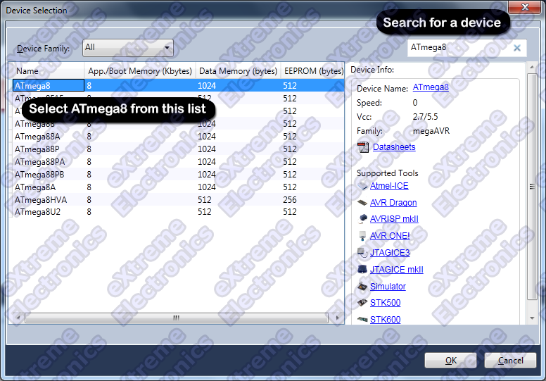
Device Selection (ATmega8 in this case)
After we completed the “New Project” wizard, we are presented with the Atmel Studio 6 main window. So let us get introduced with the various parts of Atmel Studio 6 window.
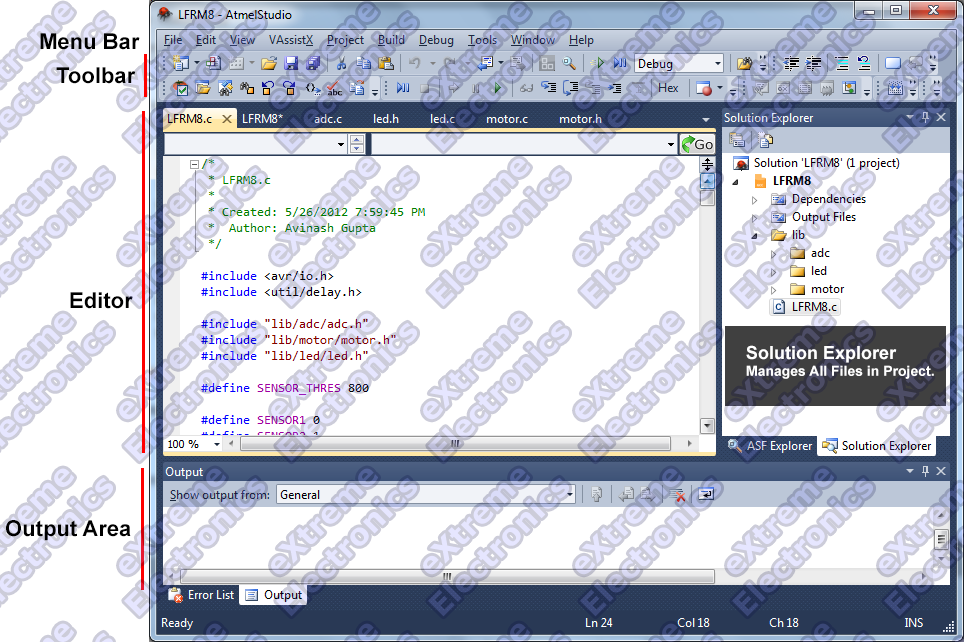
- The Menu Bar – Common in all application. This has commands for all tasks organized in sub menus like File , Edit, View etc.
- The Tool Bar – It is also common in all application. The tool bar has selected commands from the Menu Bar which the user uses often. They have small icons for each command.
- The Main Source Editor – This window is the main editor for the source files in the current project. you can load any file (in your current project) by double clicking it in the solution explorer (discussed shortly). The editor has spell check and auto complete features.
- Solution Explorer – In AVR Studio 6 a solution can house one or more projects. In our case we simply keep one project per solution. Solution Explorer is discussed in more detail in next section.
- Output Window – Most build tools like the compiler, linker etc are command line tools. When we issue command such as the Build command, their output is captured and shown in this area. Also errors or warning if any are also shown in this area.
The purpose of this part of tutorial is to understand the Atmel Studio IDE and NOT the program. So please just copy and paste the program given below without worrying about understanding the program. If you are reading this chapter in printed form, then you need to type the program given below in the editor area of Atmel Studio.
/*
 * led_blink.c
 *
 * This program blinks an LED whose positive leg is connected
 * to PORTB's bit 1, that is PB1 (IC's pin number 15)
 * the negative pin of LED should be connected to a 330 ohm
 * resistor and this resistor's other leg should be connected
 * to ground.
 *
 * ATmega8 should be clocked from a 16MHz crystal
 * Fuse bits should be set as follows
 * Low Fuse:   0xFF
 * High Fuse:  0xC9
 *
 *
 * Created: 17-08-2015 AM 11:47:49
 *  Author: Avinash
 */


#include <avr/io.h>
#include <util/delay.h>

void main()
{
   //Set PORTB1 as output
   DDRB=0b00000010;

   while(1)
   {
      //Set PB1=High(+5v), this will turn on the LED
      PORTB|=0b00000010;
      _delay_ms(500); // wait for half second, then turn it off

      //Set PB1=Low(GND)
      PORTB&=0b11111101;
      _delay_ms(500);
   }
}
The next very important thing you need to do is to configure the project. Some people thinks the program is a self contained entity. But this is wrong. This program does NOT has a vital information anywhere is the hardware in which it is gonna run. This is good because the propose of the program is only to dictate the steps need to be taken in order to achieve some results. But the compiler needs to know on which AVR chip it is going to be ran. Because each AVR chip has different amount of RAM. Compiler also generates the startup code whose task is to initialize the microcontroller to be ready to execute user program. One vital step of the startup code is to initialize the stack point to the end of RAM. As the stack grows upwards (that means decreasing RAM addresses) without proper initialization of stack pointer the microcontroller cannot run. This startup code is automatically generated by the compiler and the user does not need to care much about it. But the compiler needs to know what is the highest address of RAM is available in order to do so. So it needs to know how much RAM the current chip has. And that is indicated by the chip we selected in the above steps. This information is stored in the project file and not the program file (.c files).
One another configuration required in project at which the target processor is running. Since Atmel AVR microcontrollers can be clocked from a variety of clock sources and can be made to run at any speed below 16MHz (newer AVRs can be clocked upto 20MHz!). So we must tell the compiler at what speed our chip is running to that it (the compiler) can calculate delays properly.
This is defined as a preprocessor symbol.
Don’t worry much about the name if you can’t get it. Simply understand it like a constant which is available in all you C source files in the project.
A preprocessor symbol has a name like F_CPU (which stands for frequency of the CPU) and a value like 16000000 (16MHz)
It can be defined using the project properties dialog.
To bring up the project properties dialog you can do any one of the following.
- Hit Alt+F7 from the keyboard.
- From Project menu select <project name> Properties (last item on Project menu).
Once you have opened the project properties dialog. Navigate as shown in the image below.

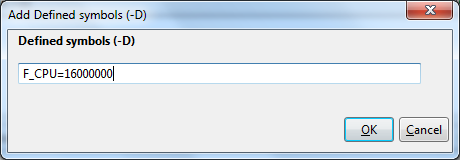
This will open up the following dialog, where you can enter the symbol F_CPU and its value 16000000.
All of our AVR development boards are clocked using a 16MHz external crystal so we have defined F_CPU=16000000
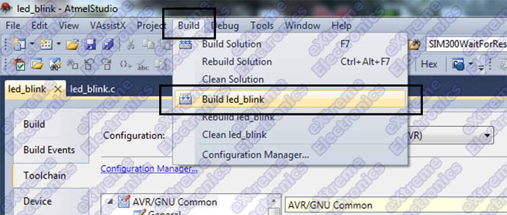
The final step is the building the project. It means compiling all the c source files in the project to generate machine code file (.o files, or object files) and then finally linking all object files to generate the executable file (.hex) file. This hex file is ready to be loaded into the microcontroller chip.
To build the project, select Build Solution from the Build menu. You can also use keyboard shortcut F7 to build the project.
If everything is setup correctly and your source files do not have any syntax error then you will get the following message.
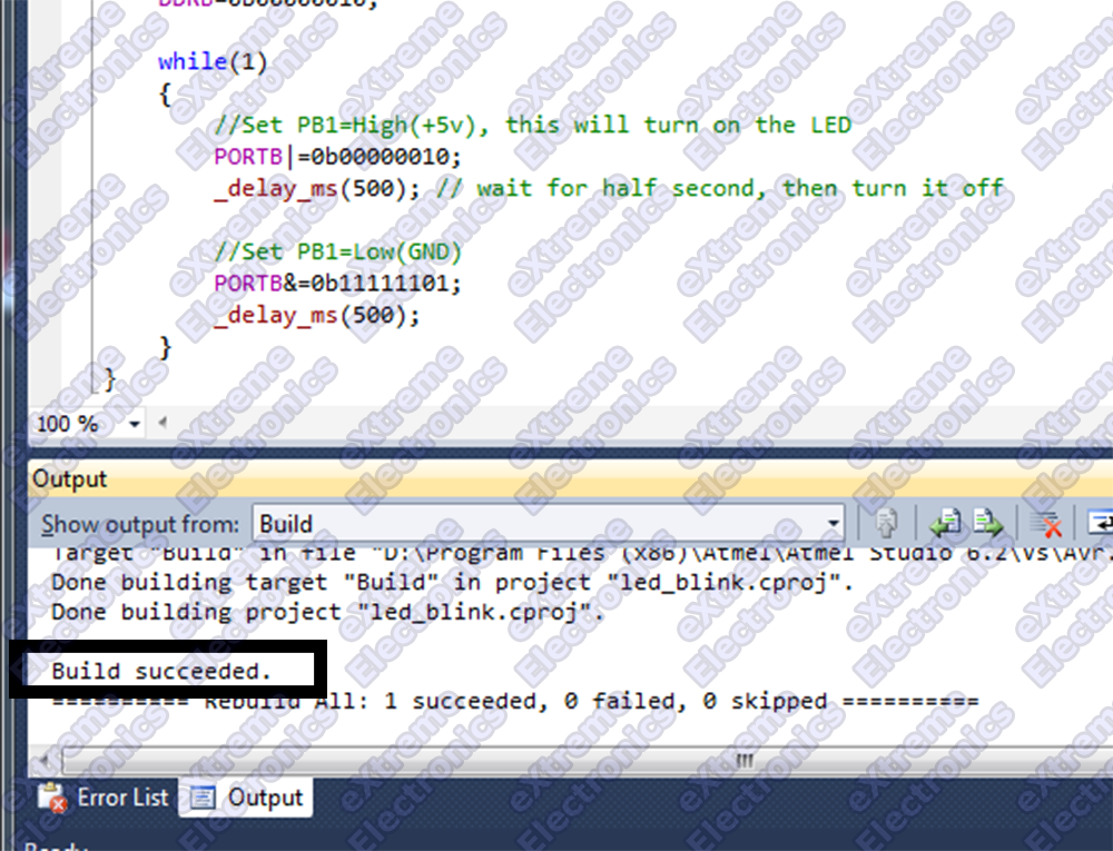
Once the project is build successfully a hex file is generated. You can use any programmer to upload this hex file to your MCU. This hex file is generated inside the folder Debug which is inside the Project folder (led_blink in our case) which is again inside the solution folder (led_blinkin our case).
How to transfer this hex file to the development board will be described in next chapter.
Facing problem with your embedded, electronics or robotics project? We are here to help!
Post a help request.


Anyone has done micro inverter project for Solar
thanks a lot Avinash! i faced a problem.. can you give a information is lcd library same for avr studio 5 and atmel studio 6.. when i build programme on atmel studio 6 using avr studio lcd library.. it happens a error just like this 1. lcd.h : No such file or directory. although i have written in a programme ….#include “lcd.h” also added the library file of lcd.. plz help.. i tried a lot but i can’t
hello Avinash, i am doing ultrasonic based 360 degree view around vehicle project in atmel studio 7 using samd20j18 micro controller using kit samd20 xplained pro kit can u plz help me in coding
thanks Avinash see u in next chapter
Hi, I get following error executing your code:
Severity Code Description Project File Line
Warning return type of ‘main’ is not ‘int’ [-Wmain] LED blink C:\Users\Mysafety\Google Drive\documents\Atmel Studio\projects\LED blink\LED blink\main.c 31
What is the cause? Solution?
Thks!
i want a code for atmel studio to interface atmel 328 with e paper display.