Obstacle detecting sensors are one of the most basic type of sensors that electronic hobbyists use. There are several methods to make cheap obstacle sensors. These simple sensors are made using a IR Rx/Tx pair or Normal LED and LDR pair(this design is most basic and is heavily affected by environment lighting conditions). These sensor may be useful for simple requirement but they have following drawbacks :-
- Can’t say anything about the real distance of obstacle.
- Give different result for different coloured obstacles.
- Need calibration (like setting up a variable resistor).
To solve these problems we have IR Range Finder Module (like one made by Sharp) but they have small range.
- Sharp GP2D12 Distance Measurement Sensor has a maximum range of 80cm
- Sharp GP2D120 Distance Measurement Sensor has a maximum range of 30cm only.
To solve all these problem we can use an Ultrasonic Range Finder Module. An Ultrasonic Range Finder Module uses ultrasonic waves (inaudible to humans) to measure distance. These module consist of an Ultrasonic Transmitter (Tx) that emits the ultrasonic wave, the waves after striking any obstacle bounces back and reach the Ultrasonic Receiver (Rx). By measuring the time it take for the whole process to complete and using simple arithmetic we can measure the distance to the obstacle. The Ultrasonic Range Finder Modules has a wide operating range of 1cm to 400cm with an accuracy of 1cm. These specifications makes it ideal for distance measurement application. These can be used for :-
- Contact less measurement of liquid level in tanks (even 4m deep tank!)
- Radars for robot.
- Obstacle sensing in Robotics.
- Speed check in roads.
- Handheld units that can be pointed on vehicles to measure their speed.
- Fixed unit installed in check booths that can click pictures of over speeding vehicles (Remember NFS Most Wanted?)
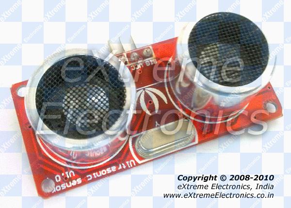 |
Ultrasonic Range Finder Module |
The reason for using ultrasonic wave are:-
- The speed of Ultra Sonic waves is 343m/s (Speed of Sound) which is not too fast for MCUs to measure accurately. Compare this with speed of electromagnetic waves (like light or radio waves) which is 30,00,00,000 m/s! So it takes only 20ns (nano second) to go and bounce back from an obstacle which is 3m away! An AVR running at 16MIPS(maximum for most AVRs) takes 62ns to execute a single instruction.
- Ultrasonic waves travels more narrow, like a beam than normal sound wave. This property helps the sensor detect the obstacles that are exactly in line with it only. The sensors can be rotated with steppers or servo motors to get a "image" of obstacle in the surrounding area (like a radar).
- Finally the wave do not disturb any humans nearby!
Ultrasonic Range Finder Interface.
These modules are designed to be used for microcontroller based applications hence optimized for it. The interface is a single pin called SIG (signal). The MCU is connected to the Ultrasonic Range Finder Module by a single i/o line. The steps required to read distance are :-
- Microcontroller make the i/o line output. (by using the DDRx Register in AVR or TRISx Register in PIC)
- The i/o line is made low (this may be the default state of i/o pin)
- Wait for 10uS
- Make the i/o line high.
- Wait for 15uS
- Make the i/o line low
- Wait for 20uS
- Now make it input (by using the DDRx Register in AVR or TRISx Register in PIC)
- Module will keep it low. Wait till it is low, as soon as it becomes high start the timer.
- After that wait till it is high, as soon as it becomes low copy the timer value and stop the timer.
- Finally we have the time required for the wave to go hit the obstacle and come back to the module.
If the pulse width is in microseconds, the distance can be calculated by the following formula :-
- Distance in cm = Pulse width/58
- Distance in inches = Pulse width/148
Ultrasonic Range Finder Interfacing Sample code for AVR
To understand our code for Ultrasonic Range Finder Interface you need to have basic knowledge about timers in microcontroller. In short a timer is a register which increments it value at predefined intervals without the need of any help from CPU. One of the use of timer is to measure the time accurately. Please note that modern MCUs have sophisticated timers with lots of configuration options and can be used for several purposes. For more details on setup and use of timers please refer to the following articles.
Here we will use TIMER1 of ATmega32 for counting the duration of pulse. The TIMER1 has 15 different waveform generation modes. We will use the default that is called NORMAL mode. The modes are selected using 4 bits called WGM13,WGM12,WGM11,WGM10. We need the NORMAL mode which is applied by setting all four bits to 0. WGM1 stands for Waveform Generation Mode for timer 1.
To setup the TIMER1 we need to setup its control registers properly. They are called
- TCCR1A – Timer Counter Control Register 1 A
- TCCR1B – Timer Counter Control Register 1 B
TCCR1A – Timer Counter Control Register 1 A
This register basically deals with the Output Compare Modes so they are used when generating PWM signal from timer. As we are using timer in NORMAL mode we set most Output Compare related bits to 0. This register also has the WGM11 and WGM10, as discussed earlier we need to set all WGM1x bits to 0. This results in all 8 bits in TCCR1A set to 0. The line below is taken from example code.
TCCR1A=0X00;
TCCR1B – Timer Counter Control Register 1 B
This register has bits related to Input Capture, WGM13,WGM12 and the Clock Select Bits (CS12,CS11,C10). We need to set the input capture related bits to 0 and the WGM1x bits to 0 too. The final thing is the CS1x bits. They are used to select a clock source for TIMER1 as per the table below.
| CS12 | CS11 | CS10 | Description |
0 |
0 |
0 |
No Clock Source (Timer/Counter Stopped) |
0 |
0 |
1 |
clki/o/1 (No Prescaling) |
0 |
1 |
0 |
clki/o/8 (No Prescaling) |
0 |
1 |
1 |
clki/o/64 (No Prescaling) |
1 |
0 |
0 |
clki/o/256 (No Prescaling) |
1 |
0 |
1 |
clki/o/1024 (No Prescaling) |
1 |
1 |
0 |
See data sheet page 110 |
1 |
1 |
1 |
See data sheet page 110 |
We are running on CPU speed of 16MHz, so our i/o clock is 16MHz. We divide this by 8 to get a 2MHz clock for our timer. This means the timer increments its value in 0.5 microsecond. We can divide the value by two to get exact 1 microsecond time base. So the TCCR1B is configured by only setting up CS11, this is written in C as follows
TCCR1B=(1<<CS11);
After setting up the timer using the two control registers, we clear the counter by writing 0 to it
TCNT1=0x00; //Init counter
After that we wait for the falling edge and as soon as it is detected we put the timer value in a temporary variable called result.
//Falling edge found
result=TCNT1;
//Stop Timer
TCCR1B=0x00;
It is highly recommended to go through the Chapter 16bit timer/counter1 in the datasheet of ATmega32. TCCR1A and TCCR1B is described in page 107 to 110 of the datasheet. Also if you are very new to C programming it is recommend to read the section Operation on Bits (Bit wise Operation) in any good book of C. It is wise to enter the field of embedded programming with good grip on C language. So don’t ask me why the "0X" was prefixed before 00 when we set up TCCR1A or what does the symbol "<<" stands on the above code line. But to help most of you I have written an article "Programming in C – Tips for Embedded Development." that may clear some of your doubts.
The code employ some error checking and preprocessor magic that may confuse you but they are necessary for
- Preventing the code to hang the system if uSonic Module has errors or Not connected. (Waiting forever for rising/falling edges). So we employ a time-out system.
- Allows you to easily change the PORT and Position where the sensor is connected.
The code depends on our LCD library to handle the 16×2 LCD module which is used to present data.
1     /********************************************************************
2
3     Example program to learn interfacing Ultra Sonic Range Finder Module
4     with AVR ATmega32 Microcontroller.
5
6                                          NOTICE
7                                --------
8     NO PART OF THIS WORK CAN BE COPIED, DISTRIBUTED OR PUBLISHED WITHOUT A
9     WRITTEN PERMISSION FROM EXTREME ELECTRONICS INDIA. THE LIBRARY, NOR ANY PART
10    OF IT CAN BE USED IN COMMERCIAL APPLICATIONS. IT IS INTENDED TO BE USED FOR
11    HOBBY, LEARNING AND EDUCATIONAL PURPOSE ONLY. IF YOU WANT TO USE THEM IN
12    COMMERCIAL APPLICATION PLEASE WRITE TO THE AUTHOR.
13
14
15    WRITTEN BY:
16    AVINASH GUPTA
17    me@avinashgupta.com
18    ********************************************************************/
19
20    #include <avr/io.h>
21    #include <util/delay.h>
22
23    #include "lcd.h"
24
25    /********************************************************************
26
27    Configuration Area.
28    UltraSonic (US) sensor connection.
29
30    in this example it is connected to PORTA bit 0
31
32    Adjust the following to connect is to different i/o
33
34    ********************************************************************/
35
36    #define US_PORT PORTA
37    #define  US_PIN   PINA
38    #define US_DDR    DDRA
39
40    #define US_POS PA0      //PORTA0
41
42
43    /********************************************************************
44
45    This function measusers the width of high pulse in micro second.
46
47    ********************************************************************/
48
49    #define US_ERROR 0xffff
50    #define  US_NO_OBSTACLE 0xfffe
51
52    uint16_t getPulseWidth()
53    {
54       uint32_t i,result;
55
56       //Wait for the rising edge
57       for(i=0;i<600000;i++)
58       {
59          if(!(US_PIN & (1<<US_POS))) continue; else break;
60       }
61
62       if(i==600000)
63          return 0xffff; //Indicates time out
64
65       //High Edge Found
66
67       //Setup Timer1
68       TCCR1A=0X00;
69       TCCR1B=(1<<CS11); //Prescaler = Fcpu/8
70       TCNT1=0x00;       //Init counter
71
72       //Now wait for the falling edge
73       for(i=0;i<600000;i++)
74       {
75          if(US_PIN & (1<<US_POS))
76          {
77             if(TCNT1 > 60000) break; else continue;
78          }
79          else
80             break;
81       }
82
83       if(i==600000)
84          return 0xffff; //Indicates time out
85
86       //Falling edge found
87
88       result=TCNT1;
89
90       //Stop Timer
91       TCCR1B=0x00;
92
93       if(result > 60000)
94          return 0xfffe; //No obstacle
95       else
96          return (result>>1);
97    }
98
99    void Wait()
100   {
101      uint8_t i;
102      for(i=0;i<10;i++)
103         _delay_loop_2(0);
104   }
105   void main()
106   {
107      uint16_t r;
108
109      Wait();
110
111      //Initialize the LCD Module
112      LCDInit(LS_NONE);
113
114      Wait();
115
116      LCDClear();
117      LCDWriteString("Ultra Sonic");
118      LCDWriteStringXY(0,1,"Sensor Test");
119
120      Wait();
121      Wait();
122      Wait();
123      Wait();
124      Wait();
125      Wait();
126
127      LCDClear();
128
129
130      while(1)
131      {
132
133         //Set Ultra Sonic Port as out
134         US_DDR|=(1<<US_POS);
135
136         _delay_us(10);
137
138         //Give the US pin a 15us High Pulse
139         US_PORT|=(1<<US_POS);   //High
140
141         _delay_us(15);
142
143         US_PORT&=(~(1<<US_POS));//Low
144
145         _delay_us(20);
146
147         //Now make the pin input
148         US_DDR&=(~(1<<US_POS));
149
150         //Measure the width of pulse
151         r=getPulseWidth();
152
153         //Handle Errors
154         if(r==US_ERROR)
155         {
156            LCDWriteStringXY(0,0,"Error !");
157         }
158         else  if(r==US_NO_OBSTACLE)
159         {
160            LCDWriteStringXY(0,0,"Clear !");
161         }
162         else
163         {
164
165            int d;
166
167            d=(r/58.0); //Convert to cm
168
169            LCDWriteIntXY(0,0,d,4);
170            LCDWriteString(" cm");
171
172            Wait();
173         }
174      }
175
176   }
Hardware Setup for Ultrasonic Range Finder Test
The test circuit will be built around ATmega32 microcontroller. The output device will be a 16×2 lcd module. So we set up a basic ATmega32 circuit. The circuit will have the following :-
- ATmega32 MCU
- 16MHz Crystal
- Reset Circuit.
- 5v Power Supply Circuit.
- ISP (For programming)
- LCD Module.
- LCD Module Contrast adjust pot.
 |
Schematic for AVR ATmega32 and LCD Connection. |
Please note that power supply circuit is NOT shown in the above schematic. You will need a 7805 voltage regulator IC in order to generate 5v from any source of 8-18v.
The above circuit is so common that you may require it as a base for several projects and experiment. For that reason we have made a fully assembled and tested unit on a professional PCB. You can buy one of them from the following link.
- xBoard v2.0 – Advance AVR Development Board.
- USB AVR Programmer v2.0 (Needed for Burning Programs to AVR MCU)
If you are using the xBoard v2.0 then you don’t need to built any circuit. Just hookup the LCD Module as shown below.
 |
A 16×2 Character Alphanumeric LCD Module Supplied with xBoard |
 |
A 12 PIN Connector is already soldered to the LCD Module |
 |
12 PIN Header For LCD Module Connection on xBoard. |
 |
LCD Module Connected. |
 |
The Whole Setup. |
 |
Connect PA0 to SIG Pin on Sensor |
Other wise you may also buy a Low Cost AVR Development Board, but it does not has in built LCD Module connector so you need to solder it your self at the free area (and also do the wiring).
Extra 5v out is available in most development board. Connect the 5v and GND from the dev board to the Ultrasonic Range Finder. Finally connect the PA0 from devboard to the SIG pin of uSonic Module.
Compile the above program using AVR Studio (compiler is avr-gcc). And finally burn the program using any ISP Programmer to the ATmega32. The fuse bits must be set as following to enable external crystal as clock source.
- High Fuse = C9 (hex value)
- Low fuse =FF (hex value)
After burning the HEX file to MCU, finally you are ready to power up the setup. When powered on, the LCD Screen Should show you the distance of the obstacle in cm. This complete our test. You may consult the video at the end of article for how you can verify the readings.
Troubleshooting
- NO Display on LCD
- Make sure AVR Studio Project is set up for clock frequency of 16MHz (16000000Hz)
- Adjust the Contrast Adj. Pot.
- Press reset few times.
- Incorrect Reading or Screen Says "Error".
- Check connection between MCU and Module (PORTA0)
- Check if Fuse Bits are set as told above or not.
- Check whether Crystal is 16MHz or not.
- Compiler Errors
- Many people these days has jumped to embedded programming without a solid concept of computer science and programming. They don’t know the basics of compiler and lack experience. To learn basic of compilers and their working PC/MAC/Linux( I mean a desktop or laptop) are great platform. But embedded system is not good for learning about compilers and programming basics. It is for those who already have these skills and just want to apply it.
- Make sure all files belonging to the LCD Library are "added" to the "Project".
- avr-gcc is installed. (The Windows Binary Distribution is called WinAVR)
- The AVR Studio project Type is AVR GCC.
- Basics of Installing and using AVR Studio with avr-gcc is described in this tutorial
- How to add files to project is described in this tutorial.
- General Tips for newbies
- Use ready made development boards and programmers.
- Try to follow the AVR Tutorial Series from the very beginning. (Remember the list spans four pages, page 1 is most recent addition thus most advance)
Video for Ultrasonic Range Finder Test
Reader’s Contribution
Mr. Uttam Dutta has extended the code to include a relay driver that turns on the relay when an object comes nearer than predefined distance. This output is then used to play a audio warning. You can see the Video here.
Downloads
Help Us!
We try to publish beginner friendly tutorials for latest subjects in embedded system as fast as we can. If you like these tutorials and they have helped you solve problems, please help us in return. You can donate any amount as you like securely using a Credit or Debit Card or Paypal.
We would be very thankful for your kind help.
Other Ultrasonic Range Finder Modules
If you are using other ultrasonic range finder module such as the HC-SR04 sensor which has separate trigger and echo line (four pin type), you may refer to the following tutorials.
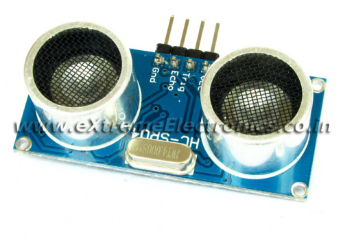 |
Ultrasonic Range Finder HC-SR04 |
Ultrasonic Rangefinder HC-SR04 Interfacing with ATmega8 : This tutorial will show you how to interface this sensor with ATmega8 microcontroller. The distance measured (in cm) is shown on a 16×2 alphanumeric LCD module. In the tutorial you will find hex file ready to burn and complete Atmel Studio 6 project with source code.
By
Avinash Gupta
Facebook,
Follow on Twitter.
www.AvinashGupta.com
me@avinashgupta.com
dear sir my name is Rakesh Patel
I am doing bachlor of engineering project i have where house condition like 3 meter of sequre. the border is make by wooden block in between that ever 75 cm there are wooden block so 3 row which has 1.5 meter long and center of each row has put diffrent colour film cansister which 5 cm away form the wall and i need to pick up all the three cansister and short out the on right position can you help to programming the robot
Here i am giveing idea about component
we are using 2 Sf05 ultrasonic sensor for front and back nagavition purpose and GP12D 2 Ir sensor for both side which we can plan to use for follow the wall.
for collocting of cansister we make gun magine kind of thing we cut round plat and then we stick plat under neat and make 4 block where we can collect cansister we stick servo motor on top to rotate round plat
we are using 2 dc motor to dirve robot which is 12 volt and battery is also 12v dc and 3.4 Amp
sir if you need more details I will send you my project plan but I need help to programming because i am not much famillary for programming can you please help me for that.
@Rakesh,
If you are NOT familiar with what you are doing then why don’t you do something that you are familiar with?
I don’t know why I will write code for you If I can have a nap in that time!
“I don’t know why I will write code for you If I can have a nap in that time!” – Best reply ever!!
Great tutorials keep up the good work.
@Brendon
Thanks ! 🙂
hey av,can u pls upload tutorials for sd card intefacing with avr.I have post this earlier & again reposting it.thanx.
@Sayantan,
Wait we are doing it! We like perfection so will take some time. Also supporting hardware is being developed.
@Rakesh
U need to give more details abt ur project if u expect help from someone… Post ur question on AVR freaks and you will get a POLITE/HELPFUL reply.. people there will be keen to help u rather than having a nap… http://www.avrfreaks.net/
People at extreme electronics give extreme replies!! wow! i luv you guys.. BTW a really nice tutorial you should have understood it clearly..
@Spy
You are WRONG burnt and smoking ic chip breath MF! Beside the FACT that avrfreaks is utterly USELESS! in that its inhabitants will merrily give you the RUNAROUND for days and weeks seems pretty damn RUDE to me. Not to mention fathead henchman police chief clawson and his “gang” of subservient non-identity no-personality followers who assuming they did know what theyre talking about (which I doubt) their ridiculous advice is so redundantly CRYPTIC you not only wind up back where you started you wasted A LOT of time in the process!
I would much rather get a sharp UPFRONT even ugly reply from Avinash, than waiting for you “CHUMPS” at avrfreaks to come thru – which (in my experience) HAS NEVER HAPPENED! NOT ONCE! NOT EVER! On the other hand, Avinash offers SOLID HELP THAT GETS THE JOB DONE! As a matter of fact, I believe Avinash establishes a precedent in this regard. A precedent which I (for one) will try to follow. So go back to bed and take your meds spy – your name aptly describes you. BTW.. regarding spies – no one has ever benefitted from guile and deception. Ever heard of a law that to each action there is an equal an opposite reaction? Ahhh nevermind.. I sense Im wasting my time.
How did politics get into this?
@W. Lewis,
Thanks for your time you took to defend me!
-Avinash (admin)
Hi Avinash,
Wonderful article, very knowledgeable.
I am sure you are coming up with a Zig-Bee tutorial very soon. Looking forward to it.
Thanks.
Mr. Avinash,
Thank you for helping me to carried out this project. Finally thing started working. But I want to share my experience.
After completing hardware and successfully downloading the Hex file I found LCD display sowing some value which is not at all the exact the distance. I tried to position the sensor in different position and changing the position of object ,but actual distance not coming. I scratch my head, reassemble the hardware, recompile the program but no improvement, then doubt on sensor, but it is of reputed there should not be any problem as you told. As I am not very efficient understanding the code. As price of the sensor little costly I am hesitating to try this project with another such sensor from you , and I almost leave hope.
Then certainly came to my mind lets play with the scale factor. I made it 0.58 , compile and downloaded, found some relevant value starts showing, but when cross checked with 1 ft. scale found showing excess value, finally with few trial I made it 3.335 and display started showing exact value. I crosschecked with different distance and found it is OK.
I checked from 5 cm to 186cm and display shows exact value.
I know this is not matching with “range finder data sheet ” but it is working.
Thank you again for providing such an exciting tutorial and helping me in different stage for building this project. Another thing Updation of dispaly little slow, i.e. when object comes in front of sensor , dispaly changed atleast after 1or 2 seccond, is it possible to overcome this thing !
Sincere Regards,
Uttam
@Uttam Dutta,
Please send your pictures along with small descriptions to my email ID.
Hello Mr Uttam Dutta,
I would like to know the details of your project on “ultrasonic with voice recording.” Specifically i would like to know more about the voice recording circuit as i have to do a similar kind of project. I would be highly obliged if you could mail me detailed description of your project along with the schematics on kartik_8582@yahoo.co.in
Thank you
@Uttam Dutta,
The fault is that your CPU is running at different speed than what is required for the above demo program. That is why you need to change the multiplication factor in the calculation. It is due to the same reason that update rate is bit slow.
Connect a 16MHz crystal and program fuse bit as described. It will work flawlessly!
@Uttam Dutta,
Please uploads pictures and videos of you latest creation so that we can share with our community.
Mr. Avinash,
Thank you for your help and concern, Yes it was problem with fuse bit,
High Fuse = C9 (hex value) , Low fuse =FF (hex value) , It was there but there was no tick mark in to the selection box and it was overlook by me.
After correcting fuse bit and restoring sacle factor everything working fine.
I am sending separately some still photograph of this project.
One question- If I want to use Port C of atmega32 in this project as D/O will I able to use it normally?
Here in this project Port A ,bit 0 is used for Ultrasonic, can I use any other bit of port A for Output i.e for ON a LED. and can I use portB or portC unused bit as I/O
regards,
Uttam Dutta
@Avinash Well seems like you found my comments offensive! I think all tht Rakesh needed was suggestions, pointers to getting started kinda stuff. eXtreme Electronics is a fantastic site no doubt abt it! Also I have appreciated this tutorial of yours. I didn’t challenge ur views that you need to thank someone for defending you 🙂 All things apart i love the kinda work being done here. keep your gr8 efforts going 🙂
@Spy,
Sorry, but I can’t change my self.
Avinash
@Avinash Well till the time u r doing good its fine don’t change yourself 🙂 and hey my comments have been edited, @wlewis part missing 🙂
Hi Avinash
I would like to find out which compiler you are using. Is it Codevision AVR or WinAVR?
I am starting to learn Codevision AVR and i was wondering if it would be possible to convert to this code to make it work with the Codevision compiler
Yuveer
Hi Avinash
I have connected up the above circuit except i am using an ATMega16 instead of an ATMega32. Both chips only differ in terms of memory so i believe it should be suitable.
When i switch on the power, the LCD displays a value and then says error. Then if i move my object a bit further/closer, it displays a value on the LCD and then shows error. The error message remains on the LCD even when i move my object further/closer,
I have configured my fuse bits as above , and i am using a 16mhz oscillator, but without the 22pf capacitors as i did not manage to buy them as yet. Do you think these capacitors could make the project work as in your video?
It does not work as smoothly as it does in your video. I can send a video of whats going wrong if you’d like.
Best Regards
Hi Avinash!
Your site make this fun & easy to learn!
– In the getPulseWidth() function, why is result fielded as a uint32_t when the TCNT1 value is only 16bits long?
– I’ve been playing around with measuring an ultrasonic distance using input capture, ever thought of doing a timer/capture example?
Hi
i have SRF06 ultrasonic sensor,how i can modify the hardware and code to be suitable for this sensor
thanks
Hey
The link to the module is working..
Any idea on where should i be looking to find it ?!
hello sir….m using ultasonic range finder SRF04 with a microntroller ATtiny 2313….m confused as to how to interface the sensor with the microcontroller
@ishaan kakar
I am not here to solve all of the world’s confusion. Bye.
sir can u give me the details or specifications of the ultrasonic range finder used for the given code
@Amber,
What details or specification?
Why you need them?
Do you want to make this demo?
Sir , this system is done based on the seeduo sensor right? Now this HC-sr04 sensor is same as the sensor used in this system if i am not wrong with only change that it has separate trigger and echo line , so sir what changes will have to be done in program to interface hc-sr04 sensor.
@Mr S Gowri Shankar,
We are the official Seeed Studio Distributor in India. So we support that sensor only. Now why don’t you either get a Seeed Studio uSonic Sensor or ask the guys from where you have purchased the HC-SR04 crap about the code? Please don’t use my codes or tutorials because they are for our loyal customers only. Good bye.
Sir,
Thank you for the reply and i remember buying a xboard v2.0 more than a year back for over 2k and it did not come with diodes for the secondary motor control although it was mentioned in the manual that it had them. Then i send enquiries regarding that and even called up but to no result now i do not remember the order Id itself anyway i understood that your sales service is not upto the mark.
Thank you for your extreme polite reply.
@S Gowri Shankar
If we are NOT upto the mark, then please tell me why are you hanging around in here ?
Only this forces me to make this place member only site.
My life is too short to talk with so many people.
Thank you for praising my politeness.
Hi Avinash,
I was searching on the internet for making a project which would be helpful in controlling the action of the water pump installed in my house.
The idea was to calculate the distance between sensor and water level and then convert it into volume (distance * pi*r^2). This volume would be continously displayed on the LCD and the volume on water hence calculated will be used to control the switching action of the water pump.
The code/hardware shown above is perfectly suitable, but the question is “Will this sensor work when the obstacle is water?”
I work as a software engineer in Mainframes…no longer in the embedded systems fileld..but i find my soul still married to microcontrollers specially AVRs.
I must appreciate the efforts you put in to train the noobs in the dark. Awesome work bro!!
Waiting for a reply!
Thanks
Ankit Raj
@Ankit,
Yes it will work, water also reflects uSonic waves !!!
Thanks Avinash!
Probably i will also have to take care about the percentage of reflection/refraction/absorption on the water surface.
I want to buy a UltraSonic Range Finder from your site..but i found that its not in the stock!
Can you give an approximation of its availability?
Thanks!
Ankit Raj
Nice program.
Why have you chosen the magic numbers – 600000 and 60000 in your program?
I guess the first one (600000) is a calculated time out value in for loop but I am unable to get on the other value (60000) which you are checking against TCNT value in your program to detect if TCNT is greater than 60000 then there is no obstacle.
So question is how did you derive the value 60000 – from datasheet of this module or from your own experiments?
Hello Avinash, When are the stocks expected for the ultrasonic range finder module?
Hello Avinash..
Greetings!!
I have few queries regarding the above circuit.
1. What can be the maximum distance between the sensor and the micro controller board.
2. I came across a sensor (similar to above) which sends data (ASCII values which corresponds to distance in cms ) serially on 9600 baud rate.
The data sent is automatically refreshed after every 500 ms.
Link below.
http://www.rhydolabz.com/documents/sensors/Ultrasonic%20Distance%20Sensor%20Serial%20Output-User%20Manual.pdf
So which sensor should I opt for PWM output or Serial output when i have to keep the distance between sensor and microcontroller board > 30 ft. Which will be more accurate?
Thanks
Ankit Raj.
Can this ultrasonic sensor be used for counting rpm of a turbine(fan)?
@Rakib
no….!!!!!!!
Nice tutorial. I have an HC SR04 ultrasonic module with 4 pins:
vcc, trig, echo and gnd.
Is there much difference in coding for an HC sr04?
Hello. im trying to get this work also. The example uses the same pin as read/write so shouldnt be too hard to do.
It works.. Just change getPulseWidth to read from echo pin and dont set Trig as input in the while loop. DONE! 😀
hi , i used usbasp programmer purchse from ur store. i used atmega 128 microcontoller with 11.0592 mhz i dont know fuse bit can u help me what is the fuse bit of it ?
@Vikas
LOW Fuse = 0xFF
HIGH Fuse = 0xC9
Pingback: An Inexpensive Robot Platform « Pointers Gone Wild
“”Distance (cm) = pulsewidth/58.””
“”Distance (inches) = pulsewidth/148.””
Is this formula only for AVR or PIC.?????
And just want to know how this formula came..!!!!
why 58 ro 148 numbers are there in the formula..????
Hello Mr Uttam Dutta,
I would like to know the details of your project on”relay driver that turns on the relay when an object comes nearer than predefined distance. The output is then used to play a audio warning”. I would be highly obliged if you could mail me detailed description of your project along with the schematics on a2mit7@gmail.com..
Thank you
Hello sir,
I want to use number of ultrasonic sensors at a time for distance measuring so did they effect each other?
As I want high range distance sensors with good maximum(10 m) as well as minimum range(5 cm) so which sensor I should prefer and do u have that type of sensors?
Does ultrasonic sensors can get distraction from other sources?
What will be the time period of delivery if I order 10 to 15 sensors at a time?
I want code for atmega16 in bascom AVR language for that sensor can you provide me that with product?
If you use a number of uSonic Sensors, fire each one by one so that they don’t interfere with each others.
Max range is 4m only
Timer period for delivery anywhere in India is 3-5 days.
Only the above code is available. No Bascom code available.
thanks because of your kindness.
hello avinash sir.. this code is for ultrasonic serial out sensor for distance measurement . can u send me assembly code for ultrasonic serial out distance measurement sensor which is interface with atmega8515. working on avr studio4?? please send me code … i am very thankful to u…..
i’m working on Atmega128. connected trig and Echo pins to its ADC pins PinF0 and PinF1 respectively.The echo pin is never getting high with obstacle in front…
In fact the LCD always displays the Error Message.
I am not able to find what exactly is the issue.
please help.
Please tell How to check that Hardware is flawless..
And my ulrasonic module is DYP me007
PLEASE can you tell me where the number 600000 comes from?
Thanks in advance
Can it detect an object which is not exactly in line with the sensor, may be a few centimeters to the left or right??
Pingback: Attiny2313 Ultrasonic distance (HR-SR04) example | CircuitDB
sir how do i convert the code for the distance measuring to liquid level measuring using the ultrasonic sensor? please help
why you don’t use _delay_us function? and why you use this kind of delay bellow?
void Wait()
{
uint8_t i;
for(i=0;i<10;i++)
_delay_loop_2(0);
}
hello sir,
please tell me how to the above code. ia have the same sensor but my board is atmega256rfr2,
any guidance will be helpfull
Thank you AV,
your tutorials are always helpful.
i have a question.
why you left shifted ‘result’ at the end of the getPulseWidth() function?
@Mohit,
Welcome. Divison is a time taking process in digital systems. While shifting is very fast. If divisor is 2 then left shifting the dividend left by one place is equivalant to dividing by 2.
Thanks for reply, i am glad that i learnt something new today
Pingback: Autonomous Sumo Combat Robot with Pneumatic Flipper - How to - Makezilla
hi, i have a doubt, why use the unit16_t?
ty!