Hi Friends, In last tutorial we discussed about Multiplexing Seven Segment Displays. So you must be very much familiar with the theory. Now let us write the code and design a small project that will make you expert in using these displays in your own projects. We will make a system that can display any number between 0-9999 using four of these displays. We will design a function Print() that we can use on latter projects to easily write integers onto displays. Once we have successfully tested this function we can add to to any project without any problem. This concept of code reuse will make bigger project both easy to make and far less painful. In this sample project we will test our function by using it in a loop to print all numbers from 0-9999.
	for(i=0;i<10000;i++)
	{
		Print(i);
		Wait();
	}
Things Required
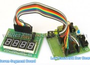
| S. No. | Item | Image |
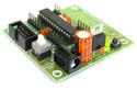
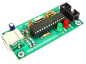
| 1 |
Contains the core AVR circuit including 5v regulator, reset, ISP. |
 |
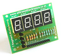
| 2 |
Four common anode displays multiplexed with driver transistors and current limiting resistors. |
 |
| 3 | Single Pin Female to Female Burg Wires Used to interconnect the two boards
|
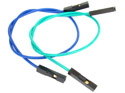 |
| 4 |
To upload the program to the development board. |
 |
These are all the things required to get started with seven segment displays. The development board and the programmer can be used with many other projects to! While the seven segment board is handy for all projects requiring numeric displays.
Making !
Connect the seven segment board with the development board using the cables as per the table below.
| Seven Segment Board | 28 PIN AVR Dev Board | |
| A | PD0 | |
| B | PD1 | |
| C | PD2 | |
| D | PD3 | |
| E | PD4 | |
| F | PD5 | |
| G | PD6 | |
| DO (DOT) | PD7 | |
| C1 | PB3 | |
| C2 | PB2 | |
| C3 | PB1 | |
| C4 | PB0 | |
| GND | GND |
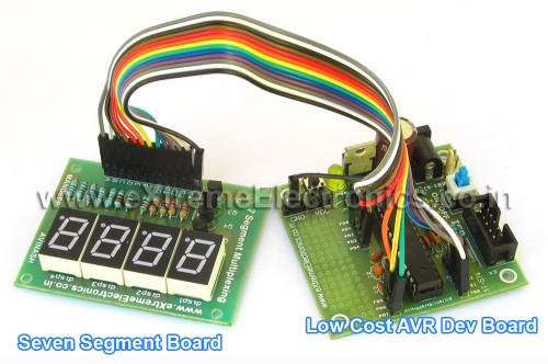 |
|
Fig. Seven Segment Display Setup |
The Circuit Diagram.
 |
|
Fig – Multiplexed Seven Segment Displays. |
The Code
/*

Description:   Program to demonstrate the use of Seven

            Segment Displays In Multiplexed Mode.
________________________________________________________

Author:     Avinash Gupta
Date:    11 Oct 08
Updated:
Web:     www.eXtremeElectronics.co.in


*/

#include <avr/io.h>
#include <avr/interrupt.h>
#include <util/delay_basic.h>


#define SEVEN_SEGMENT_PORT PORTD
#define SEVEN_SEGMENT_DDR  DDRD

volatile uint8_t digits[3];


void SevenSegment(uint8_t n,uint8_t dp)
{
/*
This function writes a digits given by n to the display
the decimal point is displayed if dp=1

Note:

n must be less than 9
*/
   if(n<10)
   {
      switch (n)
      {
         case 0:
                          //.gfedcba
         SEVEN_SEGMENT_PORT=0b00111111;
         break;

         case 1:
                        //.gfedcba
         SEVEN_SEGMENT_PORT=0b00000110;
         break;

         case 2:
                        //.gfedcba
         SEVEN_SEGMENT_PORT=0b01011011;
         break;

         case 3:
                        //.gfedcba
         SEVEN_SEGMENT_PORT=0b01001111;
         break;

         case 4:
                        //.gfedcba
         SEVEN_SEGMENT_PORT=0b01100110;
         break;

         case 5:
                        //.gfedcba
         SEVEN_SEGMENT_PORT=0b01101101;
         break;

         case 6:
                        //.gfedcba
         SEVEN_SEGMENT_PORT=0b01111101;
         break;

         case 7:
                        //.gfedcba
         SEVEN_SEGMENT_PORT=0b00000111;
         break;

         case 8:
                        //.gfedcba
         SEVEN_SEGMENT_PORT=0b01111111;
         break;

         case 9:
                        //.gfedcba
         SEVEN_SEGMENT_PORT=0b01101111;
         break;
      }
      if(dp)
      {
         //if decimal point should be displayed

         //make 7th bit high
         SEVEN_SEGMENT_PORT|=0b10000000;
      }
   }
   else
   {
      //This symbol on display tells that n was greater than 9
      //so display can't handle it

      SEVEN_SEGMENT_PORT=0b11111101;
   }
}

void Wait()
{
   uint8_t i;
   for(i=0;i<10;i++)
   {
      _delay_loop_2(0);
   }
}

void Print(uint16_t num)
{
   /*


   This function breaks apart a given integer into separate digits
   and writes them to the display array i.e. digits[]

   */
   uint8_t i=0;
   uint8_t j;

   if(num>9999) return;


   while(num)
   {
      digits[i]=num%10;
      i++;

      num=num/10;
   }
   for(j=i;j<4;j++) digits[j]=0;
}


void main()
{
   uint16_t i;

   // Prescaler = FCPU/1024
   TCCR0|=(1<<CS02);

   //Enable Overflow Interrupt Enable
   TIMSK|=(1<<TOIE0);

   //Initialize Counter

   TCNT0=0;

   //Port B[3,2,1,0] as out put
   DDRB|=0b00001111;

   PORTB=0b00000001;

   //Port D
   SEVEN_SEGMENT_DDR=0XFF;

   //Turn off all segments
   SEVEN_SEGMENT_PORT=0X00;

   //Enable Global Interrupts
   sei();

   //Infinite loop
   //Print a number from 1 to 9999
   while(1)
   {
      for(i=0;i<10000;i++)
      {
         Print(i);
         Wait();
      }

   }
}

ISR(TIMER0_OVF_vect)
{
   /*

   This interrupt service routine (ISR)
   Updates the displays

   */
   static uint8_t i=0;

   if(i==3)
   {
      //If on last display then come
      //back to first.
      i=0;
   }
   else
   {
      //Goto Next display
      i++;
   }

   //Activate a display according to i
   PORTB&=(0b11110000);
   PORTB|=(1<<i);

   //Write the digit[i] in the ith display.
   SevenSegment(digits[i],0);
}
Pingback: Interfacing Temperature Sensor with AVR Microcontrollers - LM35 | eXtreme Electronics
your code is really good.i make the project with great succesfull and with little bit different code.i think i can expand this for four displays.your code inspire me.thnx a lot
Hi Nick,
🙂 Thanks for your response , I am very happy that my work helped you.
You can easily expand the code for 4,5 displays.
Nice to meet you 🙂
Hello avinash
the program for counting 0-999 its working but I am using stk500 with ATMega16 m using PORTB for Display, PORTD three pins for 3Xseven segment display , my question is why its working with PORTD PIN 0,1,2 only , I have changed only where u have activated 0,1,2 to 5,6,7 is it ok , but still its not working plz help me out …this is my c code :
[CODE REMOVED] – Site Admin.
Dear Avinash,
In this program you have not defined Digit its giving error
Dear Avinash,
In this program you have not defined Digit its giving error
I think that is array .
*************************************
A SMALL BUG IN ABOVE PROGRAM REMOVED.
*************************************
– Site Admin.
in the above program digit[i] was not initialised.now if my program is long and takes some time to reach print(i) in main loop then i will reach the interrupt routine before print(i).
ie we expect that our interrupt comes at least after the 1st print(i).
what will the output be in this case or what error will it give?
Thanks for your deep analysis!:)
As varriables are stored in RAM and For uninitialized varriable contains unpredictable data.
The best way to test is to simply remove the Print() call at all!
And then run it so check what shows up
🙂
Thanks Avinash. Can I buy you a drink?
@Emeka
🙂 Sure !!!
Pingback: AVR Project - Digital Stop Watch with ATmega8 | eXtreme Electronics
How come you never call the ISR(TIMER0_OVF_vect) function? How do you end up printing the numbers since it is never called.
Hello Kelvin,
The function ISR(TIMER0_OVF_vect) is an ISR i.e. Interrupt Service Routine. It is called automatically by the hardware (in this case the TIMER) when it needs attention of CPU. Do you get it now ???
Hello Avinash
I the above program helped me lot..good man nice work……but if I want like digit should blink same as we put blinking bulb in diwali for decoration…like 1 comes it blinks for some time the 2 comes and so on…..is it possible? can you tel me how
hi all
any one knows how can I blink the numbers or alphabets which comes on seven segment display , same like diwali bulbs it comes then go ,comes then go……
hi sir
i want to know that how to simulate it in proteus.i am trying but not able to get expected result. can u plz help …
thak you.
Why you use this: “for(j=i;j<3;j++) digits[j]=0;" because it`s never call.
Because the variable "i" will be 3 when exiting from while(num) so j=3 and "j<3" is not true, then all the code in section "for()" it will never be executed.
@Claudiu
Don’t use your brain too much. Leave it to the CPU (or the MCU) to execute the code
Its the difference between theory and reality.
Why will i=3 when the while loop break?
It will be 1 when the number to be printed is 1 digit say 3
It will be 2 when the number to be printed is 2 digit say 21
when the number to be printed is single or two digit then this code is used to fill leading 0.
Got anything ???
Give more emphasis on doing thing not finding faults in others.
Sorry if I am bit harsh.
Ok, sorry for that. I understand now, you are right.
When I`ve make my multiplexed 7segm code, I didn`t put zeros in front of the digits, so that`s why I didn`t understand.
PS: your code is much better and easy to implement.
@Cladiu
Glad you understood it. Coz if you leave that line, then there may be left out digit from the last print. Thats why I fill them with Zeros.
Example:
You printed 435 first. The display will show it fine. Then say you wanna print 7 then it will show 437 instead of 7. The 4 and 3 are shadow left from last call. So we fill zero in unwanted places.
Got it ???
Hi…
btw. great site 🙂 Thanks.
Just wondering is there any reason you couldn’t move the 330 Ohm resistors to the Anode end? Therefore only 3 resistors needed instead of the 7 on the PORTD/Cathode end.
Hell0;
when i compiled your program i get the following errors in AVR studio 4 please help i am beginner and i am using atmega32
../multiplesevensegments.c:134: error: ‘TCCR0’ undeclared (first use in this function)
../multiplesevensegments.c:137: error: ‘TIMSK’ undeclared (first use in this function)
@Mohammed
Did you configured AVR Studio project to use ATmega32 ???
Please reply ASAP or your comment will be deleted.
i am sorry i was configuring it to atmega328p now i got it thanks but please do tell me should the bc557 be connected to positive terminal of the battery since iam using common anode seven segment leds
The entire project is wonderful. However, I’m using PIC16F877 and the compiler is mikroC. Can you help me out with converting these line of codes into mikroC?
ISR(TIMER0_OVF_vect){ ...}// Prescaler = FCPU/1024
TCCR0|=(1<<CS02);
//Enable Overflow Interrupt Enable
TIMSK|=(1<<TOIE0);
//Initialize Counter
TCNT0=0
//Enable Global Interrupts
sei();
@Scada,
The following code is for PIC16F877A using HI-TECH C
https://extremeelectronics.co.in/code-snippets/multiplexed-seven-segment-display-using-pic16f877a-and-hi-tech-c/
Great job avinash ..:) thank you…But I would ask u How to write program to display data onto 4-digit multiplexed 7-segmentdisplays? in asemmbly not C….?so controlling for digits by PORTD(D0…D3) and controlling segment’s leds by PORTB(B0…B7)..by using atmega32 microcontroller…
Waiting for ur help thank u
Hi! I have problem with 3x7segment display. After writing hex to mcu i get it working, but somehow it’s malfunctioning (made video with slow motion to better understand problem http://www.youtube.com/watch?v=QAGBkIZ13DI it does look like it turns 2 sections of lcd at a time) Any solutions in changing code? I use 7segment lcd’s with common + and atmega32 with internal oscilator (i think at 8mhz). I use WinAvr + Programers Notepad. Making hex i get 3 warnings:
c:98: warning: function declaration isn’t a prototype
c:135: warning: function declaration isn’t a prototype
c:134: warning: return type of ‘main’ is not ‘int’
Tryied compile code for attiny2313, but it doesn’t alow, geting few errors.
@Arturas,
I think you have used wrong type of transistors, so when they should be in “on” condition they are actually “off” and vice-versa. So check your transistors. Use exact type shown in tutorial.
great tutorials!
I have done a 5-page PDF of the seven segment MUX tutorial with PagePlus,which i will gladly send for you to put on the site
Thanks, for this code.
But there is a thing I don’t understand in the interrupt function:
ISR(TIMER0_OVF_vect)
{
static uint8_t i=0;
if(i==2)
…
The variable “i” is declare with the value “0”.
The test “if(i==2)” will never be true.
And the last line “SevenSegment(digits[i],0);” will alway display the digit “1” because the i++ line before.
Can you explain me ?
@Domos
can’t you notice “static” before the variable declaration?
Consult a book on C for definition of “static” variable rather than guessing whatever you like.
I do not think I was aggressive in my question, unless this is due to my broken English.
Programming is just a hobby for me
hi,
Avinash
you r awesome man.u done a great job.i must say ur teaching skill on avr is great.easy to understand and applicable for beginners.why don’t u write a book for the beginners???it’s a great idea.Are u start working on 8*8 dot-matrix display??if so then post ur tutorial about dot-matrix.i m thankfully waiting for this.and once again god bless u………..u r absolute genius.
hi,
i read the tutorial about multiplexing three 7 segment and i have segment lcd with 40 pin its model twv1302n and i need help to apply the multiplexing theory on it
thank you alot
Hello !! your logic is good but why do you use switch-case statement for 0-9 counting. The better (shorter) way (i think) is to make an array first containing all codes for displaying 0-9 digits. Now whenever a number is to be displayed, the array will itself call that code in its respective number for e.g. if 2 is to be displayed then the 3rd element of array should give that code to 7segment. Do u understand ? If yes do u agree ?? Thats my approach of displaying digits .
@Shayan,
Can you write the complete code, test it and submit ???
I’m using Proteus to simulate your Stopwatch circuit. I have it working but the multiplexing flickers too much and the counter takes 15 seconds to count from 1 to 2, then 15 seconds from 2 to 3 etc. Any idea on how I can speed this up? Thanks for any help or ideas.
@Avinash Did u get the mail i sent u of the program in which u have asked for the example to display digits using an array ??
Can multiplexing be seen via simulation ?? On PROTEUS ??
Can multiplexing be seen via simulation On PROTEUS ??
great work
nice job done!!!
only one request!!!
it happens with many people in learning phase that they
don’t read technical details and start experimenting so
it happens that they ask few questions, which seems absolutely silly for us, like the one above about static variable,
try to be little polite, you are doing a very nice job of teaching people free of cost, that’s a very good task, but it happens that sometimes you are too harsh
Anyways you rock man!!
@Willian,
The problem is simple enough to be recognized withing seconds! The thing is slowed down by a factor of 16.
In tutorial it is clearly written that the code is wriiten for a AVR running at 16Mhz. Have you set this frequency in Proteus ???
Have you set the fuse bytes to enable external crystal ?
Why don’t you built the circuit by following 100% of the steps as told in the tutorial ?
Why you are simulating it at all ??? Simulation is required during the development of the firmware. When you are getting 100% per-developed and tested code then whats the need of simulation ?(Thats too without setting of the Proteus properly). In this case you are debugging Proteus using the firmware (the exact opposite of what its meant for). Now you have found a bug in your proteus setup (instead of the firmware) so go correct it. Bye
Hi Avinash
i am thinking of implementing this segmented display in a project in class i am using ATMega16 on an STK500 board. My questions are two fold
1. Would i still need the resistors shown in the schematic for PORTD and B knowing that these ports on the STK500 usually have pull up resistors associated with them.
2. I need an idea of what peripherals to configure since am using the Code Vision AVR C Compiler software.
3. Could you explain the fucntion of the wait loop and the timer 0 interrupt.
Thank you
Kola
@Kolawole Hi, to answer some of your questions…
1) the resistors are current limiting resistors not pull ups.
2) not sure haven’t used CodeVision or STK500.
3) have you read the comments in ISR routine?
On the ATmega328P, you want to set TCCR0B for the Prescaler on Timer0.
sir,
Is this RTOS?
Sir
Please give c code for avr atmega16 6-7segment display
clock.
Pingback: Multiplexed Seven Segment Displays. | eXtreme Electronics
Hi Avinash.
Im from Msia. Im a beginner to this AVR Atmega 32. im quite interested in your coding for 7 segment. btw..i have an assignment which need me to do a project which involve 7 segment display using AVR ATmega 32. but i have no idea what kind of project and application to do which implement the 7 segment display. can you give any suggestion?? can you help me?? TQ
@Hanslina,
If you have never used seven segment display before it is suggested that you go with a temperature sensor project. In that you used a temperature sensor like LM35 and display the result in a muxed seven segment display.
And please don’t use more than one question mark, it is unnecessary and looks ugly !
You should have written Malaysia in place of Msia it looks better.
Hey! Thank you a lot!
I didn’t believe, I got it to work.
But when setting the prescaler to /64, the display is flickering. Setting the prescaler to /8, I have some kind of ghost shadows. Do you have any idea, where to change some timing settings, to get rid of the shadows?
Greetings from germany
@Nico,
Attach external 16MHz crystal and set fuse bytes as, HIGH BYTE=0xC9 and LOW BYTE =0xFF
Hi Avinash!
Thank you for the fast reply.
Well, it runs at 16MHz crystal and fuse bits are right.
But I solved the problem by switching these two lines in the ISR
from:
PORTB|=(1<<i);
SevenSegment(digits[i],0);
to:
SevenSegment(digits[i],0);
PORTB|=(1<<i);
Which of course makes sense. You can't switch to the next position, without prior switch on the right Segments. Maybe, you want to correct that.
Greetings!
Mr. Avinash,
how we interface matrix keypad and multiplexed 7segment display, it may require atmeg32 dev. board, but what will be the code.
regards
uttam
hello
im the beginner of learning avr and i face with a problem when i complie the source code on codevision compiler it has error on first line
i mean this line
#include
now what i should do?
avinash i need the flowchart of this program please
@Thuraiya,
So make it from the program? What are you waiting for? Its easy !
in “Connect the seven segment board with the development board using the cables as per the table below.” does it same when using atmega 32?
@Ridhwan,
No! it is NOT the same.
sorry avinash sir
as u said
“Attach external 16MHz crystal and set fuse bytes as, HIGH BYTE=0xC9 and LOW BYTE =0xFF”
but it does not work even i have attached a 16 MHZ external crystal ….
my atmega16 not responding now for downloading ISP …
Please Reply Fast 🙁
@Warish,
You have to purchase this board.
Along with microcontroller.
http://store.extremeelectronics.co.in/40-PIN-AVR-Development-Board.html
Sorry.. sir i have already purchased a devlopement board so i can’t purchase now….
be sure i will purchase some other stuffs from ur store within some months !
heyy avinash i’m beginner cn u send me codes for making digital clock on seven seg…but it should only show minutes and seconds
Dear Avinash,
Your effort helping others.
Please let me know that I have three 7-seg displays
and want to display float values like 1.23 or 12.3 .
Integer values are working successfully but problem
in decimal point values.
How to handle it?