Digital IO is the most fundamental mode of connecting a MCU to external world. The interface is done using what is called a PORT. A port is the point where internal data from MCU chip comes out or external data goes in. They are present is form of PINs of the IC. Most of the PINs are dedicated to this function and other pins are used for power supply, clock source etc as you have seen in Part III of my tutorials. Ports are named PORTA, PORTB, PORTC, PORTD etc. The pin configuration of ATmege8 mcu is shown below
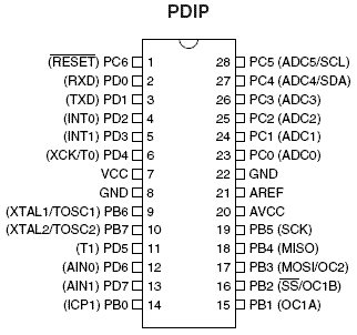 |
Fig – Mege8 pin configuration |
As you can see the pins are labeled PC6,D0,PD1…etc . A port say PORTD is a 8bit register you can set it to any value like
PORTD=0xFF;
In C language prefix 0x signifies a hexadecimal number here 0xFF means decimal 255 or binary 11111111 which means all the bits in the register is high. A high value on the output port gives +5V and 0 gives ground. You can set the value of PORTD to any required value. This is the basic of digital interface. You can connect LEDs, and switch them on/off from your program. You can connect speaker and produce desired frequency by quickly switching the PORT pin on/off to get sound. But these PORT can source and sink limited current that means you cannot directly connect devices that need heavy current. But by use of proper hardware you can interface power demanding devices like motors and relay. By the use of proper relays you can control device of any voltage, current and power like a huge mains water pump!
These digital IO pins can also be used to read in the data from external world. In simplest case you can use them to read the state of switch or sensors. This way you can make a keypad for your device.Using AVRs digital IO pins.
As I said each AVR MCU has several IO ports named A,B,C etc. You can find out their physical location by looking at the pin configuration given above. For example Port C’s 0th bit is at PIN 23 of the IC. You must have also noticed that there are additional names given in brackets near the PINs. This is due to the fact that IO pins have more than one function. The primary and the default is given near the pin while the secondary and tertiary functions are given in brackets. The secondary functions are huge life saver for us. This is where these chips starts showing their power.
Additional Port Functions
Basically any digital IO is carried by 1s and 0s that we can do with simply accessing the PORTs then why secondary functions? Yes, you can make any functionality(ex serial data transfers etc) in software by simple manipulating the PINs or reading their values. But that “common task” which is commonly required in MCU world are already implemented for you and that’s too in hardware. Yes, the AVR MCU has several inbuilt hardware called the peripherals.
- USART for serial communication with PC and other devices. Example uses -A robots controlled by PC and connected to it using only 3 wires. -A digital room thermometer that logs daily temperature and can be connected to PC to view the records in special software
- ADC-Analog to digital converter used for advance sensor interfacing Example uses -Reading the value of temperatures or amount of light falling on a sensor.
- SPI- Serial peripheral interface. It is used for serial communication between digital devices(EEPROMs, Data Flash, LDC modules etc)
- Output compare pins can be used to generate digital wave forms automatically. They are highly configurable. Example uses – Controlling speed of DC motors. – Simple sound and frequency generation without making the CPU busy. CPU just sets the desired frequency and is free to do other things and the hardware does it all.
There are many other functions to help you I have just touched the surface here to just get you an idea. More about them in next tutorials.
Accessing digital IO in C
Each PORT in AVR has three related Registers.
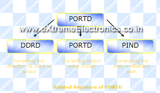 |
Fig – PORT D’s related registers. |
DDRD: This is the Data Direction Register of PORTD. The bits in this register set the data direction of individual pins. The direction for each pin can be input or output. Port pins are made input when you want to read data from them ex a light sensor. They are made output when you want to use them to output data ex blink led or control a motor. To set any pin as output set its bit to ‘1’ and to make it input make it ‘0’.
For example …
//Make portd-0 as output
DDRD=0b00000001;
In this example portd’s 0th bit is made output while rest pins are input.By default all IO port pins are input i.e. ‘0’
PORTD: After you have set the pins to output now you can control them with is register the values you write here will be visible on the related pins of the MCU. For example
…//Make portd-0 high
PORTD=0b00000001;
//Wait one sec
Wait(1);
//Make it low
PORTD=0b00000000;
…
PIND – Port Input : When you set any port pin as input you have to read its status using this register. Suppose you have connected a switch as shown below
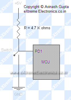 |
Fig – Interfacing a switch to an Input PORT. |
then as the ports are initially input type then you need no initialization. You can read the state of key/switch by simply reading the PIND. It will be ‘1’ when un pressed and ‘0’ if pressed. Sample code
...
if(PIND & 0b00000010)
{
 //Switch is not pressed
 ...
}
else
{
 //Switch pressed
 ...
}
...
If you don’t get the line if(PIND & 0b00000010) then you need to improve your C skills see Yashwant Kanetkars great book “Let us C” it has a chapter on operation on bits. Also check out my brothers blog http://learning-computer-programming.blogspot.com it is a great place to learn basic C/C++ programming.
The above example told you how to take input from real world using sensors or switches. But key interfacing is not so simple care should be taken for a problem called switch de bouncing. Which I will teach in next tutorial.
Now you know the basics of digital IO in AVR MCUs which is very fundamental topic in MCU world. The concepts will be used in any projects you go for. After reading this article you will better understand the “Hello world” Project created in the last tutorial. Goodbye for now meet you in next tutorial. And do not forget to post your suggestions and opinion. I will be glad to see them.
Check your understanding! Take a 1 minute test.
Pingback: Part IV - The “Hello World” project | eXtreme Electronics
you are using always DDRD in PORTD sections. but never PORTD is that ok or maybe there is mistake?
Hello Tedybear,
Thanks for pointing out my mistake. I am correcting it just now. I am very thankful to you.
Hello Sir,
I liked your tutorial. I am able to understand it . You are doing a GREAT JOB for we beginners.KEEP IT UP.
Hi Avinash,
Excellent work dude!! Really impressive..
The five parts are excellent refreshers. Is there a next part to this…part VI..
Can you please add a link to next part in current part 🙂
Hello,
@Sumanth
all parts are here
https://extremeelectronics.co.in/category/avr-tutorials/
Hi,
Thanks for the great article
I just have a query. I just wanted to know if anyone knows a reason why the following case happens
DDRC =0b00000010
I have set Port C1 as input pin
Just for curiosity I did the following stuff
PORTC |= 0b00000011
so now the bit 0th and 1st in portC register is set.
All the bits in PIN register are not set. If I do the following code
if(PINC & 0b0000010)
the Bit1 of PINC is set as I dont see a reason why as I am just checking whether bit 1 in PINC is set or no. Why would it change the bit value for PINC.
@Rohan
First thing DDRC=0b00000010 set PC1 as OUTPUT and NOT input as u said.
Also as PIN register holds the actual value available on pins, then if u had connected a switch on PORT C then the PIN value will be changed if you press or relase the key.
Hi Avinash,
Sorry I made a typo mistake it was DDRC = 0b11111101.
I understood with what you meant that PIN value reads the value inputted by other external electrical component on PORTC. But still when PORTC 1st bit was set and when I checked whether PINC register 1 bit is set or no the debugger indicated that value is not set but after finishing the check it changed the value of 1st bit in PINC1 to 1 and that whats confusing me. The debugging was done using AVR Studio.
HI Avinash,
I am attaching a piece of code, it is not similar to one written in my previous post and try it with AVR studio
void readInputAtPortC1()
{
// when I check whether PIN C1 is set or but over here
// the pinC 0 value is set which I dont see a reason why it //should happen as PORTC0 is o/p port
if(PINC & 0b00000010)
{
//Debug stuff
}
}
void main()
{
DDRC =0b00000001;
while(1)
{
PORTC |= 0b00000011;
readInputAtPortC1();
}
}
@Rohan
PLEASE READ THE DATASHEET !!!!!
When in input mode setting a bit in PORTx register enables the INTERNAL PULLUPS on PINs. This means if left unconnected the PIN value will become HIGH
HOPE U GET IT 🙂
ALSO PLS USE FORUM FOR DISCUSSION NOT THIS PAGE 🙁
http://forum.extremeelectronics.co.in/
Thanks for the reply
very nice article sir ! 🙂
it’s really help me to open mid about MCU world.
thank you.
keep updae sir :D.
Bro!! you rock!!! \,,/
Pingback: Interfacing Ultrasonic Rangefinder with AVR MCUs | eXtreme Electronics
Pingback: 4x3 4x4 Matrix Keypad Interface with Atmel AVR Microcontrollers | eXtreme Electronics
Hello Sir,
As far as i know here we are using byte processing. Can you please tell me about processing one bit at a time.
I heard somewhere about “_BV()” sort of thing. But I am unable to understand.
@Nipun
see gcc manual _BV() is described in details!
explanation is nice…..
excellent tutorial
I searched a lot to learnt micro-controller programming but never got a material so well organized and so clear
you are doing a good job
keep it up
Pingback: Using Shift Registers with AVR Micro - AVR Tutorial | eXtreme Electronics
dear friend will you please tell me with which software you make your drawings? they are clean and extremely beautiful.Avinash please help me… hope you will reply me
@Nikhil,
Dear friend,
Cameras don’t take photos its the photographer!
Cars don’t win the race its the racers!
Software don’t draw images its the artist!
I am sure you have been working with the same software. Is its plain old MS Word 2003! any one who know computer knows MS Word!
dear avinash , with which program, you make all your drawings?
thanks avinash
great article. Where can i find the Facebook Like Button ?
how to operate single pin of port?
Give me syntax of that.
for example in pic micro controller I use
((register name)bits.(bit name)).
simple and very easy to understand…thank you sir
where is the continuation to this topic?? switch debouncing?
Pingback: Simple Single Motor Control using AVR ATmega16 - eXtreme Electronics
Sir, how can we access a single Pin of Port. Are AVR microcontrollers bit accessible.
@Ankush Chavan,
please see this https://extremeelectronics.co.in/avr-tutorials/programming-in-c-tips-for-embedded-development/
Sir, please help.
how to make 1 switch controlling 2 leds alternately.
When switch pressed at the firs time, led1 is on ( led2,off )…
then switch released, led1 off.
And when switch pressed again, led 2 on ( led1 off )
then switch released, led2 off.
Thank you very much.