Welcome to the 3rd part of RF Communication tutorial. In the last two parts I have introduced the basics of RF Communication.
- RF Communication Between Microcontrollers – Part I : Introduction to RF Communication and Modules.
- RF Communication Between Microcontrollers – Part II : Algorithm and general description of data transfer.
Part III will be covering mostly the practical part, i.e. we will build a complete & working data transfer system. Here you will get circuit and program to implement the solution. The application is very simple in this case, just to transfer a byte of data from Tx station to the Rx station. Once you implement it and get it working you will have enough information and experience to make other RF based projects.
I request all users to follows the instruction exactly as given (unless they are smart enough to know what they are doing). The most important thing in this article is timing of the MCU, so
- Use the exact frequency crystals as used in the designs.
- Write High Fuse = C9 (HEX Value) and Low Fuse FF (HEX Value) to enable external crystal.
Hardware
We will have two units. One is Tx (Transmitter) and Other is Rx (Receiver). Both units are based around ATmega16 MCU(you can use ATmega32 also) on external 16MHz crystal. On the Tx unit PORTC will act as input. While in Rx unit it will act as output. The value at PORTC of TX unit is constantly sent over the air to the RX unit where it is latched on its PORTC. That means whatever value you put in the PORTC of Tx station is available on PORTC of Rx station (8bits or 1 byte). We will connect 8 micro switches on the PORTC of Tx station and 8 leds on the PORTC of Rx station. For testing you can press keys on the Tx side and corresponding LED on the Rx side will glow. Simple!
You can then use the same techniques of sending/receiving data in any other application, like SWARM robotics.
 |
RF Module Tx + AVR ATmega16 |
 |
RF Module Rx + AVR ATmega16 |
The above two schematic gives detailed connection of AVR ATmega16 (or ATmega32) MCU with RF Modules.
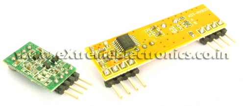 |
RF Modules |
Note About the Schematic
- Power PINs of MCU are not shown but must be connected properly.
- BC548(NPN) transistor and two 4.7K resistor forms a very simple NOT gate(inverter). This is because in RS232 communication the "idle" state is HIGH to make idle state LOW we have use the inverter.
- You can use a low cost ready made avr development board for quick and easy experimentation.(like this one). It has inbuilt power supply, crystal, reset circuit and ISP port(and much more) Only you have to connect the transistor and RF modules that’s it! You can easily program the MCU by using USB AVR Programmer.
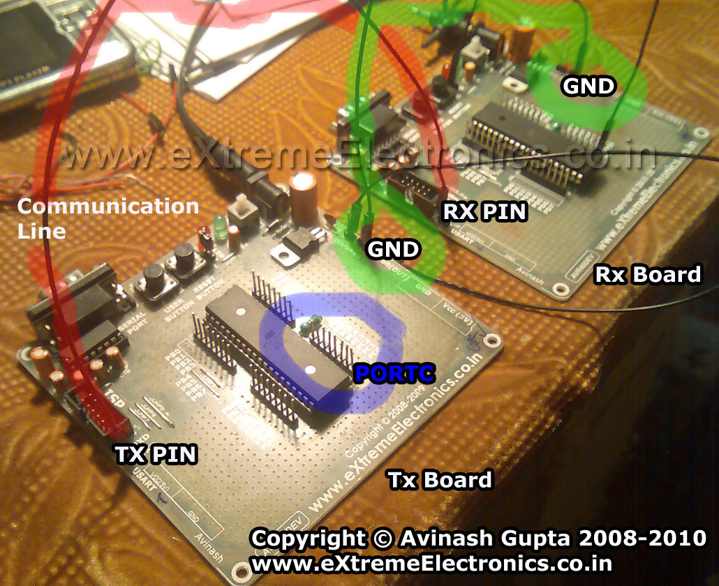 |
RF Communication Test |
Software
The software is written in C language and compiled using the open source compiler avr-gcc. For project management AVR Studio was used. I have used my fully buffered, interrupt driven USART library for usart related job. The library comes in two files.
- USART.c
- USART.h
These files must be copied to the current project folder and added to AVR Studio Project. How to add a file to avr studio project is given here.
Some important functions of USART library are as follows
USARTInit();
Initializes the USART of AVR MCU. The parameter is the UBRR value. What is UBRR? Its not the topic of this article! I assume that you know about the Basics of RS232 communication and have knowledge of USART. Don’t worry much if you don’t know that. Just leave this article and read the following articles
UWriteData();
This function sends a byte of data over the Tx channel.
UDataAvailable()
Returns the number of byte of data currently waiting in the fifo queue.
UReadData()
Reads and returns a byte of data from the buffer.
Complete Listing of Tx.c
#include <avr/io.h>
#include <util/delay.h>

#include "usart.h"

void main()
{
   //Initialize the USART with Baud rate = 2400bps
   USARTInit(416);

   //Enable Internal Pullups on PORTC
   PORTC=0xFF;

   /*

   Keep transmitting the Value of Local PORTC
   to the Remote Station.

   On Remote RX station the Value of PORTC
   sent on AIR will be latched on its local PORTC
   */

   uint8_t data;
   while(1)
   {
      data=PINC;

      /*
      Now send a Packet
      Packet Format is AA<data><data inverse>Z

      total Packet size if 5 bytes.
      */

      //Stabilize the Tx Module By Sending JUNK data
      UWriteData('J');  //J for junk

      //Send 'A'
      UWriteData('A');

      //Send Another 'A'
      UWriteData('A');

      //Send the data;
      UWriteData(data);

      //Send inverse of data for error detection purpose

      UWriteData(~data);

      //End the packet by writing 'Z'
      UWriteData('Z');

      //Wait for some time
      _delay_loop_2(0);
      _delay_loop_2(0);
      _delay_loop_2(0);
      _delay_loop_2(0);
   }
}
Complete Listing of Rx.c
#include <avr/io.h>

#include "usart.h"

void main()
{

   uint8_t i; //Clasical loop varriable

   uint8_t packet[5],data=0;

   DDRC|=0xFF; //All Output

   //Initialize the USART with Baud rate = 2400bps
   USARTInit(416);

   /*
   Get data from the remote Tx Station
   The data is the value of PORTC on Remote Tx Board
   So we will copy it to the PORTC of this board.

   */

   while(1)
   {
      //Wait for a packet
      while(!UDataAvailable());
      if(UReadData()!='A') continue;
      while(!UDataAvailable());
      if(UReadData()!='A') continue;

      while(UDataAvailable()!=3);

      //Get the packet

      for(i=2;i<5;i++)
      {
         packet[i]=UReadData();
      }

      //Is it ok?
      if(packet[2]!=((uint8_t)~packet[3])) continue;

      if(packet[4]!='Z') continue;

      //The packet is ok

      data=packet[2];

      //Now we have data put it to PORTC
      PORTC=data;
   }


}
Downloads
- Complete Atmel Studio 6 Project for Tx
- Complete Atmel Studio 6 Project for Rx
- HEX File for Tx
- HEX File for Rx
- Proteus Simulation for quick testing
Videos
Comming soon !
By
Avinash Gupta
me@avinashgupta.com
My Facebook Profile
|
RF Modules |
is it really necessary to invert the data?
@Bittusrk,
As I said before starting the article “Do as I say” or interpret the results your self. If it was not necessary then why would I have done it ?
I did lots of experiment before posting this article and I posted the setup which performed the best. If you are in the mood of re-inventing the wheels then you are most welcomed to waste your time!
Nice project!
I am just about starting a similar RF project.
@Avinash
Cool down! My fault. Sorry
What is the maximum possible baud rate of the system,should it extendable,what is the tested range of praposed system.
Thanks Avinash
I want to know about antenna whether it will be used for a distance of 3meter or not.
Your tutorials are just best and you have done nice job for the students.
Thanx in advance.
@Ravindra
Use about a 20 cm antenna. The range is good. Signal is available through out a normal size house.
depend on the module you buy, you can use antenna calculator online to get the antenna length.
What is the maximum possible baud rate of the system,should it extendable
thnks a lot dude………………….
cant we use internal oscillator ………….?
Hi Avinash
first of all nice work n thanks for the lovely tuts…
I was trying to do the same thing ( which u did here ) with the same modules however not with AVR but NXP LPC2148 (ARMTDMI-S)… following are my questions…
1. As ARMs work at 3v3 instead of 5v what transistor will be appropriate for the NOT gate?
2. If you happen to have the experience with ARMs what are the considerations to be taken in designing the same.
3. Is it necessary to use the NOT gate if some authentic and high quality RF transmitters and receivers are use instead of the usual ones?
4. If you happen to know some other better methods or modules for wireless communications ( esp. for ARM microcontrollers ) please do tell…
waiting for your reply…
thanks in advance
shashank
can i set the POL bit in the UART register rather than use an external inverter
hey avinash,
no offence to you.i really like your site and i have bought some stuff from you earlier.i really feel you are talented.but isn’t it wrong to speak rudely to the ppl who are following your blogs so closely and really appreciate your work?i am referring to bittusrk first comment on this article.he was just asking the reason to invert the data.you should have told him what would happen if you dont invert the data.what are the pros and cons of doing so or if you really are busy you shudnt have replied.but i dont find that any way to reply to somebody.i know its your site.but isnt it running only because of the people visiting this site and the ppl buying your great products?if the only purpose of teaching the ppl is not served then what is the point of the site?
i am still telling you i have no grudge against you and i really appreciate your talent in this field.thought of just telling you my opinion on this topic.sorry if it sounded rude.
@Gaurav,
I got angry just because he (Bittu Sarkar) asked the question whose answer was already there in the article. You cannot know my problem as you cannot get the chance to see hundreds of silly comment posted here(because I delete them straightway). I try to give as much information as required to understand the concept and apply it practically without much trouble. If people don’t get basic stuff they shouldn’t be reading this at all!
Some people ask “can you explain while command” while others are too smart and remove the pull up resistors from the I2C lines and say “It is NOT working”.
The only thing I don’t like is the “approach” some people take to solve a given problem. I get angry on people whose approach I don’t like. While people which right approach gets as much help he/she wants.
Other people who gets hard replies from me are the one with very poor common sense. I think no one can help them (so how can I).
Imagine you just bought a 100 PIN fine SMD IC (say a very modern radio communication IC) that has a 600 page datasheet. And has very complicated communication mechanism and you don’t have much experience in professional programming. And if your setup does not works the first time. Then what would you do? Pick up the phone and call the dealer that his IC is not working! or Try to read/research more and debug the code?
The first method is very easy BUT IT IS NOT GOING TO TAKE YOU ANY WHERE because 99% chances are that the IC is All Right and Only your setup is faulty. That is an example of WRONG approach to solve a problem.
@ Avinash
i agree with you. People should read articles carefully before they post any comments or doubts.
@ avinash
I forgot to ask you one question. What is the max baud rate for this setup?
thanx thanx thanx….
thanx for saving me from searching circuits for rf comm…..
hey….plz help me out its urgent…i’ve made the circuit but my microcontroller is giving lots of error in programming….
I’m using CODE VERSION AVR software….
what should i do???plz help me avinash…
ne more thing i forgot to mension on above post…m using atmega16L…
its giving error that its not able to open the included file avr/io.h
@Shashi,
Its written for avr-gcc how will it compile in Code Vision ???
Please don’t use this site to show your foolishness to the world !
den wats the solution sir???
i dont knw much about uC…m just a biginer….
m asking for help…i’ve been waiting for the 3rd part for long time sir…:(
@ Shashi
I’ve been working with uC’s for a couple of weeks and been programming C since late January, i’ve followed avinash tutorial to understand it all, really informative and well written, then wrote my own code, both with polling and interrupts, works great with parallax transceivers! you have to understand that you NEED TO DO YOUR OWN RESEARCH, you can’t write on a forum and expect one answer to do all the work for you, there are ALOT of things you MUST figure out by yourself or im afrid you will never make it…
@Niclas
Thats what Most Indian* Student/ Hobbyist fail to understand. Please don’t expect any one is going to do your homework.
I have to delete many such comment every day. Some even get hard replies from me.
* No racism intended here as I am Indian too 🙂
i just learned about I/P and O/P port in a workshop for obstacle detection using codevision, before 3 months…
in these 3 moths i was having my semester…still studied/experimented a lot on uC…n nw i’ve reached to UART…
….
still searching for avr-gcc…
thanx avinash sir and niclas…
@Shashi,
“Still Searching for avr-gcc”
What does that means ???
This whole site is about avr-gcc only !!!
Did you forget to read this
https://extremeelectronics.co.in/avr-tutorials/part-iv-the-hello-world-project/
Not every one is as rich as you to purchase Code Vision Compiler. I can’t recommend then to Go and Buy Rs 10,000 Compiler.
im using AVR studio , AVR studio includes the gcc compiler, just run and compile!
AVR studio can be found here:
http://www.atmel.com/dyn/Products/tools_card.asp?tool_id=2725
and ofc WIN-AVR, google it and youll find it ^^
PS. you need both (and i suppose its WIN-AVR that includes the gcc not AVR-studio) DS.
@Avinash
“Not every one is as rich as you to purchase Code Vision Compiler. I can’t recommend then to Go and Buy Rs 10,000 Compiler”
1st of all this is a very harsh and unnecessary comment. Nobody is foolish enough to “buy a Rs 10000 compiler”. People are smarter than you think. The crack for this software is not that difficult to obtain.
@Vivek
That was not as Harsh as the comment your about to receive !
People of No use like you uses the CRACKED software. No Company can use a CRACKED software. I never recommend any one to use CRACKED software. It like being a thief. The guys who developed CodeVision is Much Much Smarter than you are.
If no one is foolish enough to buy then the CodeVision guy must be foolish. But this is not the case, this implies that you are foolish.
Moral of the Story
Please friends never use Pirated Software. If you cannot afford to buy then Please use free alternatives. Because when you develop an embedded application its ultimate form is a commercial product. If you have learned to use a Paid software (when you were in learning phase) then you have to use that software also for any of your commercial product. And if your company supplies product through out the world( ultimate aim of any company) and you use a Cracked software, Code Vision Guys will sue you in no time !!!
So better use free software even at your learning phase(unless you are rich).
If you can buy CodeVision then its good but if you cant buy it use avr-gcc.
plz dont fight wid each other…k i accept my fault…
neway m not a rich person or else i would have been using readymade remote control modules…n yes it was very harsh reply from ur side…
i’m working with codevision avr becoz i got it in the workshop itself…in indore most of of the workshops r using this software…and i cant argue wid them to use low cost software so as to reduce workshop fee!!!…
n one more thing i would like to say….
not every one is as intelligent as u r!!!…
Sir, I build the whole setup as shown in circuit. I am using ATmega 32 and using your Programmer, I dumped the code. i adjusted fuse bits as given. I tested Tx pin using LED. its working. I think the problem is in receiving side. I used 16MHZ crystal. I am not getting the data in receiver. I tried all ways. I connected the tx pin from transmitter to rx pin of receiver. Please help me to find out the solution.
I want to know what has to be done for communication between 200 to 300 meters with different obstacales in between and other RF noise signal.
regards,
Uttam
Thanks avinash your tutorials are excellent and full of info for beginners like me
Hello
don’t shoot me if this is a stupid question.
But does it also work with a ATMEGA8535 (reciever) and ATMEGA16 (transmitter)??
and is there a possible way to use the internal frequantie of the MCU?
many thanks
@Lieven
Hello,
Yes it can work with ATmega8535. If you wanna use Internal Crystal Of MCU then you have to change the UBRR value according to the CPU Frequency and the baud rate required. All these are discussed here.
https://extremeelectronics.co.in/avr-tutorials/using-the-usart-of-avr-microcontrollers/
Hello
I would like to use the same freq ,internal 16mhz and baudrate of 2400bps.
In the USART.C i found this
#include
#include
#include
#include “usart.h”
void USARTInit(uint16_t ubrrvalue)
{
//Setup q
UQFront=UQEnd=-1;
//Set Baud rate
UBRRH=(unsigned char)(ubrrvalue>>8);
UBRRL=(unsigned char)ubrrvalue;
/*Set Frame Format
Asynchronous mode
No Parity
1 StopBit
char size 8
*/
…….
do i have to change this
UBRRH=(unsigned char)(ubrrvalue>>8);
UBRRL=(unsigned char)ubrrvalue;
to this? from the formule ( ubrr = (Fosc/(16*baudrate))-1 )
UBRRH=416;
UBRRL=416;
or do i have to change more?
many thanks
Hi Avinash,
I am not able to download the following,
Complete AVR Studio Project for Tx
Complete AVR Studio Project for Rx
Is there some error or thess projects is removed?? Where can i find them alternatively if not provided on the above links?
@Newbee
The files are live and easily downloadable. I tried just now!
I finally got this working. [:)]
@ Arifuddin Sheik
what was your fault? Becuase I can’t get this working. And the circuit is correct.
thanks
hi avinash,
well i want to change the Crystal freq to 12Mhz. n i m using 315Mhz RF module. is it good to work with 12Mhz crytal n 315Mhz RF module. i know for dat i hv change few lines in the code n i can do dat. just pls tell me weather ur codes r flexible for it or nt. otherwise i m comfort to work wid your specified instruction.
i m using crystal of 12mhz and the ubrr value is 311. my rf modules are 433mh himark made rf modules.
this is not working . tell me the prob is it mandatory to use 16mhz.and that 315 mhz rf modules?
hi
thanks for your wonderful tutorials
are the tx &rx module in Proteus simulation program or any other program ?
because i have project and i want to simulate it before doing it
thanks
Hi,
firstly hats off to u and thanx for explaining the rf communication so elaborately….m doing my last year engg nw n interested in rf… dis article really helped a lot in clearly some of the basic concepts which i ws stuck in…u cn say m a beginner in dis field n searchin for a project application using rf communication…
thanks
Sir,
I’m working on my final yr proj which is based on “Swarmbots”.I would like to employ RF communication for the same using a PIC microcontroller(16F877A).Is it possible to use the same logic as above with PIC too?..Kindly reply.
Thank you,
Akhila.
@Akhila
Why NOT ?
thank you sir.
Sir;
Your tutorial really helps me a lot. I have questions to ask you, it might be a simple questions but I really can’t figure it out.
The question if I want to transmit mp3 audio using transmiiter and the transmitter is controlled by the ATMEGA16, how I do I input the mp3 audio (let say if the mp3 audio is from laptop audio jack) to ATMEGA16 (which pin), do I need to use ADC?
I really grateful if you can teach me. Thank you for attention and time.
@Aini,
First clear out the basics. MP3 is a digital audio format in compressed form. That means it is only 0 and 1. The audio output from laptop can be directly feed to a headphone speakers. And since we know a speaker (in the headphone or earphone) has got no digital logics in it. This clears it out that the audio which is feed to it is NOT digital.
The mp3 files in the Harddisk is digital, which is read by the software (like Winamp) and decoded by CPU (which is No doubt digital). Finally we get an uncompressed digital output. But still the output is digital. The next step is done by the sound card which is really a good quality DAC (and also ADC for input). Now the CPU feeds this uncompressed digital data to the sound card which convert it to analog waveforms. Which is available at laptops audio jack.
So you need to feed this to AVR ADC and get converted it to digital form.
The whole concept cannot be explained in single comment.
Thank you for your reply. It helps me a lot.
Hi
Thanks for the helpful article. I’m confused about the way you use UQFront and UQEnd in usart.h,usart.c.
Could you please explain me how it helps the execution?
Thank you very much
@Prasad,
Its simple implementation of a FIFO Queue! May be you should take some Computer Science Class! Because it out of scope of the current discussion. If I were to discuss how to implement a Queue it would take another three articles.
Hi
thanks for the reply. I understood how you are implementing it but how did you manipulate RECEIVE_BUFF_SIZE is 64.
is that in data sheet?
Thanks
hye, can you tell me what is the suitable rf module for voice transmission? cause right now, im using 433MHz rf module which is can transmit and receive data at 4800bps (transmit 600 bytes per second), but there is someone said to me that i need at least 4kbyte per second for voice sampling however he don’t know any high speed module. is he right? if yes, can you suggest what is the suitable rf module? thanks
@Zaz,
To transmit a Sound which is limited to less the 4KHz frequency(Human Speech Band), you need at least a 8KBps (kilobyte per second) link. This is the worst quality sound that is just sufficient to carry only what human can produce from their mouth. Other method is to use a compression algorithm but they are hard to code and run on small micros.
You can easily transmit/receive sound via analog mode (say FM) technology.
you said 20cm should be enough for a house.the rf module which i bought has max range of 100m.to exploit max range what type of antenna should be used?
Tats really cool man.helps a lot
I got couple of questions for u.
-what is the max range achieved wit this system..??
-someone has asked this before n i guess u din reply to tat..-can i use a single reciever for multiple transmitters..??
thanks
God bless.. 🙂
This project is really help me in making my wireless automation project . i have replaced the outputs to toggle and connected relays through ULN2803 darlington IC i get good range 100m line of sight..i hav tried it before also from science prog website.I have one doubt is it c\necessary to connect NOT gates to TX and RX.
I have seen similar projects on websites they have also used inverted RS232 communication.
hello
can i use the shy-j6122tr(http://www.ekt2.com/_files/141%20RF%20MODULE%20TXRX.pdf) rx-tx modules in this project because as far as i know these modules uses manchester encodind and does not support uart
Avinash ji,
Thanks for the hard work.
Your A,A,D,~D, Z is an excellent idea, that helped me.
In fact i changed the 315 tx-rx set 433mhz, thinking its is not working, when physical line was replaced by rf.
Today i was just searching for an appropriate inverter as the always high (mark) was consuming a lot of current at the remote.
The receiver spec says 10 micaro amp load, which may not drive an op-isolator. needing amplifier to invert.
I used earlier bc107as simple inv. but not sure with 10mu amp base crt.
Your saying “Do as I say” is the right thing, else u’d have to explain this much, with no certainty that young man will understand.
Its a great pleasure to see ur solution.
I can complete the proj in this calender year itself!!
Cant wish you a Happy (Invader’s ?)New Year .
Have a nice season.
regards.
K
avinash ur website is awesome….by reading your blog i learned about rf modules which i have been trying from 1month
Can both RF modules be integrated on the same board, in order to have bidirectional communication?
10x
@AKILA
HAVE U COMPLETED THE PROJECT?
i would want to know whether we are required to construct the same power supply as u have provided or can we use another external power supply in the form of batteries etc plz suggest as our project is a radio frequency beacon tracker and we need it to be portable
also plz suggest modifications required for our project in terms of the circuit provided by you i am working at 433mhz frequency band
@bosco
Yes you an use batteries.
but a 9v batteries would do
with modification
do you know of rx-tx rf pair at 433mhz with a rssi for power levels
Hi. I am using 315MHz ASK modules to communicate with two ATMega8 boards. The master board has the transmitter and the slave has the receiver, with BC107 inverter. The master sends “AA 55 FF 30” (without quotes). The receiver checks the string and then puts on an LED. To see if the string is received properly, I programmed so that the received byte is tramsmitted again on the RS 232. This works well with a cable on RS232 interface.
The code is simple:
ISR (USART_RX_vect)
temp = UDR;
while (!(UCSRA =(1<<UDRE)
;
UDR=temp;
With RF, at the receiver, after the inverter, i.e., at the ATMega Rx pin I get the string properly, seen on GTK term. However, the MC transmits back "AB 55 01 95" consistently.
why does the MC change the data? It is because of this that the program does not recognise the correct data. This is not noise, because it this consistent. I tried otehr data, but similar issue occurs, the data at the Rx point is OK but the MC transmits converted data.
Can someone help?
hey i want to now where would i get the sm-tx 01 and sm-rx 02 i searchd at lamington mumbai i didnt find it do u now of an outlet where i could purchase it in mumbai
You will get these at Visha Electronics, opposite police station, first floor, Lamington Road. They give components at proper prices too.
Hi. I posted a problem i am facing on this expert forum regarding the rf communication between two atmega8 boards on 22 march above. I ahve seen some other circuits where the transistor inverter is not used. But when i directly connect the idle low output of the rx module to the idle high rx of the MCU, the reception stops. I have not used the transistor inverter on teh transmitter. Can someone help?
Hey avinash,
That was a really helpful tutorial. I tried it with a new micro-controller called mbed and it worked out perfectly fine. Now , I wanted to have a two way communication . So i bought 2 different pairs of transmitter and receivers working at different frequencies. One pair works at 315 Mhz and other at 433 Mhz. But there still seems to be interference caused by each other. Do you know what could be done to prevent this?
Same problem. Did you find a solution? I’m guessing i need to put a filter o the antenna of the receiving modules.
hey avinash
In your usart.c library file
in USARTInit(); function you have not enabled RXEN..
Isnt it necessary?!
Although i tried this project and it worked awesomely fine 🙂
Sorry dude!!
Didnt see library properly!!
My mistake! 🙂
hey avinash !!
this was realy a great tutorial.
it cleared many of my concepts.
i want to know will the settings in the usart.c and usart.h files work for atmega8 as well…
or i will have to make some changes in the codes…
can i simulate this project in proteus ??bcoz ur schematic seems to be image from proteus …how to simulate tx and rx bcoz there are no library of them in proteus???
Hello Avinash,
First of all, your tutorials have helped me immensely, thank you so much.
I have been implementing many of the projects in your tutorials using Atmega328p MCU’s and am trying to do the same here. For all of the registers, I have compared the Atmega16 and Atmega328p datasheets to implement the same functionality on the 328p. The problem I cannot figure out, is the USART interrupt vectors. When I compile the code, I get a warning: “‘USART_RXC_vector’ appears to be a misspelled signal handler.”
In both datasheets there is mention of “USART_RXC” in the ISR sections, however, I do not understand why USART_RXC_VECTOR is accepted by the compiler for the m16 and not the m328p. Can you please help me?
(I do see that in “USART.h” there is the line “#define USART_RXC_VECT USART_RXC_vect” which is noted to change for each MCU, but I dont know what it would change to for the 328p, if at all because the “USART_RXC” ISR is listed as the same thing for both MCU’s)
Thank You
@Jake
Please use this page to find out the name of ISRs
http://www.nongnu.org/avr-libc/user-manual/group__avr__interrupts.html
For ATmega328p the name for USART receive complete interrupt is “USART_RX_vect ”
Hope it helps.
Dear Avinash Sir,
I am planning to do a wireless communications project using AT89S51 and these RF pairs…would you please suggest me what type of antenna should i use for it.As my PC will be the master and robot will be the slave..how should i interface my PC to the Tx. Thank you for all the hard works you put in to help us new robot makers.Thank u once again.
Avinash,
The page on interrupts did help, thank you. I’ve had to delay working on this specific tutorial for a while since the school semester started, but I have been working on an RFID system for my senior design project using many of the principles I’ve learned from your tutorials. I should finish it by December and I’ll try to post it on youtube so others can learn from it too.
Thanks,
Jake
dear Avinash
this was realy a great work!thank you so much.
would you mind to put any timing diagram or datasheet of this kind of RF module here,I tried it but never found any thing!
thanks again
Dear Avinash sir,
Firstly loads of thanks for such a great hard work and making things easy for begineer’s like me:):)
Sorry if my question is silly, I hope you will answer
I am trying to experiment your RF module using Atmega32 microcontroller. But I saw in some internet pages that USART can be used only for wireless communication and even from my friends. Is it so?. The code available in this RF module Part III is for RF wireless communication only right??
Thanks in advance very much sir. Looking forward for your valuable reply asap.
Hello avinash sir…
i m a Ist year eng.. student…
Your tutorials hv cleared lot of my problems.
Now.I am trying to implement your project of tx and receiving data..
but i m using atmega8 at the transmitting end..and atmega32 at the receiving end..
plz sir,kindly tell me is this really possible..
if yes, where do i need to make the changes in the codes..
Sorry..if i m asking smthing foolish..
bt plz help me..
have you written these codes for atmega16..????
Thank you sir..
geek..
Yes. Why not ?
It is very clear from the above article!
thanx..sir for your reply…
but … here i have another issue…
plz help me out..
sir..kindly tell me ..that do we need to use only sm-rx-02 ask & sm tx 01 ask rfmodules…only
or i can use any other rf module also….
i have purchsed a Rs.250 rx tx pair…
but dont know whether is it…the same which u have mentioned here…
thanx..
geek
Thanks sr. I would like to use this tutorial to make a simple project but I need to know:
How much is the maximun distance between the Tx and the Rx?
Cause I need 90 meters without line of sight
Hi Avinash, your tuto is awesome, i’m from mexico and this help me a lot, but i have a question and some doubts, i was trying to send data from my pc to the TX uC but what i want is to receive it in the RX uC and show the characters sended in a LCD display 16×2, with your USART library is posible using the UWriteString function? and redirecting the data to the lcd display with your LCD library? I hope you can help me with this
Avinash me again I hope you can help me, I implement your code but anything seems to happen, i have to make some changes to the library cause I’m using atmega48 and the name of the registers is not the same like this
rxen= atmega16
rxen0= atmega484
and so on with the others, i changed this and it compile without and error, i also have to change the void main() to int main() cause when compiling that part caused a warning so i changed it.
My baud rate is also 2400bps but i’m running with 20MHz crystal and because of that according to my datasheet table of UDRR the value must be 520 for both TX and RX obviously.
But sadly nothing occurs int the receiver, the leds don’t glow, when i measure the voltage in the RX pin of the uC, and i press a button in th TX module a quick change of voltage occurs, so i think the uC RX is receiving data but it doesn’t send it to the portc.
If i measure voltage in the pin TX of the TX uC or in the data pin of the TX RF module nothing happends when i press the buttons… as i told you before just happen in the RX pin of the RX uC of RF module.
I don’t know what to do i all the code is the same i check carefully the name of the usart registers to make the modification to your library i don’t think that it could be a problem all seems to compile ok without errors and warnings.
i want t buy the RF rx-tx pair …plz menion the price of a pair
Hello Sir,
I am already using the USART of one of my atmega32 to communicate with the PC so i cannot use its TxD and RxD pins. Can i use other pins (except txd and rxd) for communication between two atmega32 microcontrollers? Please reply as soon as possible. My email id is : kartik_8582@yahoo.co.in
Thanking you
Hi Avinash,
I’ve been reading these articles about RF communication, and they are very useful (Thanks a lot for your har work).
I have two boards that include both of the RF Modules. What shoul I do with he anntenas? Do I need two? or can I use one antenna?
If you have some time, please email me.:)
Hi,My project is based on visible light LED. My transmitter and receiver is ready and struggling to interface with microcontroller to send real data . I can send signal(analog/digital pulse) upto 1m which is enough for me .My qestion is can I connect USART TX pin to my transmitter in one side and Rx pin of another microcontroller to other side since my transmission medium is light? Alternatively what can I use? I really need some help and looking forward to hear from you.
Hey Himel, For my project, i need to transmit analog signal wireless. I am able to transmit digital signal between two atmega32 micro-controllers. What do i need to change to transmit Analog signal. which ICs are suitable for ADC and DAC ? Kindly reply ASAP. Thanks in advance! 🙂
Have you connected two microcontroller wirelessly? Can you please explain your physical connection?
hi.your tutorial has cleared many points. but i have a question.
actually i have to make a Rx and Tx for my major project.and the project is to correct the LOS of Rx nd Rx..can this pair of tx an rx be used for this project.?
kindly do ans of this question.its really urgent.
hi,
the below mentioned website is copying your articles and publishing them in their site.Being a fan of your website thought its my duty to let you know.
http://www.theengineeringprojects.com/2012/01/wireless-communication-between_1500.html
@Mr. Vinay,
Thanks for reporting!
what are the application of this project………
hello Avinash sir
Thanks for your tutorials..
That Not gate idea was Awesome..Not only it did logical inversion of data,but also converted it as per the RS232 standards.
Without wasting much of your time,I have a conceptual doubt.Sorry if it is silly.
You connected Rf 434 receiver with 9 volts/12 volts,directly while the datasheet says the maximum operating voltage is 4.5 to 6 volts.When ever I have worked on Rf 434 I always give it 5 volts Vcc,and it does work.
sir , i want to transmit adc data through usart ,
i have try , but the data sent is only 0-255 , that is rx side the adc data displayed is only 0-255,
only 8bit data is transmitted.
so how can i modify the usart.c and usart.h to transmit 16bit data.
The series of 3 articles about RF module was very helpful for us to do our project. I’d ordered RF module from extreme electronics store. We are obscure about Vcc to be supplied to Tx & Rx. Its indicated in Rx Vcc=3V but there is no such label on Tx. Does Tx require 5V and
or does it work with 3V only?
Hi Avinash,
I’m working on a RF remote to control a bunch of relays and triacs. My design’s sort of similar except that I didn’t use the inverter transistors. The remote is battery powered for which I’ve tried to keep the power consumption minimal through the use of sleep modes. To transmit a signal I power on the Tx, send the synchronization byte, the data byte and then the 8-bit crc, power off the Tx and finally go back to sleep mode. This series of events is interrupt-triggered. The problem is when my Tx is inactive, I keep receiving noise from the Rx. How can I deal with this without the use of any special encoders/decoders (such as HT12E/HT12D)?
can i simulate this circuit at any software?
@Juwel,
Why you want to do that?
@ juwel no you can’t.
The series of 3 articles about RF module was very helpful for us to do our project. I’d ordered RF module from extreme electronics store. We are obscure about Vcc to be supplied to Tx & Rx. Its indicated in Rx Vcc=3V but there is no such label on Tx. Does Tx require 5V and
or does it work with 3V only?
This is pure gold man, great work!!! this is going to help us very much. Thanks a lot!!!
sir we were trying to wirelessly communicate between two mcu using usart (n rf 434 module) but we were getting negative value on the data pin of register what should we do?????
If you expect any reply then please use proper English! Why you have used multiple question marks?
Hello Avinash,
Other than maintain RS-232 standard or buffering the signal, Is there any need for the inversion of the signal? Because, when TX pin on MCU#1 is high TX module input is Low and Rx module output will become low and finally MCU#2 RX will go high.
If we connect the Modules directly without inverting, when MCU#1 TX goes high MCU#2 RX will become high. So, the net effect is same.
Hey,
I am doing a similar project but using Pic18f4620 and Microchip Zigbee module.I am facing problem in the programming part of it.
Can you please help me out?I have gone through various documents but no use and the deadline date is nearing.
Please help!!
@Samidha, how much time you expect it would take to help you? and what you expect, how should I help you?
I am not sure as to how the send and receive functions are framed out.SSo if you could help me with some link or document which would guide me through the programming part of it..or maybe some sample program of similar kind…
I need to read temperature from LM35 sensor and transmit it to the coordinator where it will be compared with a threshold level and a msg will be transmitted back to switch on/off a fan at the end point..
I need to complete the programming part within 10 days…
and I have no clue..
Can you help me out in any way??
Hi, Your tutorials are really great 🙂
We’re using Atmega8 with internal crsytal 1MHz. Chosen baud of 2400.
I’ve question about external antenna design. What should be its shape and length and any other specification required?
Also, do I need to increase signal strength?
It works for about 2 meters range only with using a straight wire of 20cm as an antenna..
Thank You , hope for your reply.
Suket
umm hi, you know I have been trying to send analog data through rf, and I did accordingly whatever you wrote. Yup I got results, in the portc, the digitalize analog data.:p…. Credit goes to you. But I want to show the data on hyperterm from the receiver mcu . So using ‘utoa/ is enough right? Just a lil help required cause m not getting the data in the hyperterm. But as I can see everything is working awesome.
Thanx in advance. U deserve that, many thanx.
can we connect 7400 ic as “not gate” instead of connecting transistor and resistance?
“while(UDataAvailable()!=3);” ……….Can you explain what does this line means??
@Deep,
It means wait till 3 bytes are available in USART FIFO Buffer.
Hi, can you explain this sentences which I find in the coding for Rx?
” while(UDataAvailable()!=3)”
Thanks!
respected avinash,
can you please explain the use of this statement : while(UDataAvailable()!=3);
Hey man could you suggest some nice ebook to get my hands on the USART for AVR mcu in detail.
good evening sir
am using avr atmega 16A PU1045 microcontroller for the above circuit given.Am almost done with the RX TX circuit, the reset pin is working.I connected led’s to the 15th pin of the TX board and 14th pin of the RX circuit.On fluctuating the supply to this led on TX circuit, the brightness of the led on the receiver side fluctuates but the problem is on pressing the keys on the transmitter side the corresponding pin on receiver side does not glow 🙁
I had checked my circuit many times, I had checked the mcu for its fuse bits external crystal oscillator frequency.
I don’t have much guidance for avr atmega16 here sir you are my last hope to complete this project.Please give your priceless advice for my problem.
Thank you
@Priya,
more input is required from your side to get to any solution.
So it is suggested that you move this discussion to our forum.
http://forum.extremeelectronics.co.in/
Dhansu Coding especially while implementing the Queue Part.
Please provide me the Proteus Schematic of these two projects. My email ID is internetuser2k11 {at) gmail (dot) com
https://extremeelectronics.co.in/avr-tutorials/rf-communication-between-microcontrollers-%E2%80%93-part-iii/
https://extremeelectronics.co.in/avr-tutorials/ultrasonic-rangefinder-hc-sr04-interfacing-with-atmega8/
sir how to send multiple packet like ADC and another packet ,
i have one remote temperature control project i can send ADC value and set point value but only ADC value packet send but set point value show 000
Hello Avinash,
I am very keen on experimenting with the Wireless RX and TX described in your tutorials. I will be placing my order for these modules along with two 40-pin Development Boards.
However, I find that the schematics given in Part III are not very clear. I cannot read the values of the components. Please refresh the schematics in the tutorial or mail me at chi239@rediffmail.com.
Thanks.
Hello Avinash,
I purchased two Atmega16 Development Boards along with two pairs of TX/RX modules from Extreme Electronics a few days back and put together the project as described in your tutorials.
Being on the wrong side of 60, I took the easy way of downloading the hex files directly from your website and burning them on the microcontrollers. However, the project did not work as desired. But your code files (with slight tweaking – considering the fact that I’m using Atmel Studio 6 as against your AVR Studio 4) worked just beautifully!
Hats off to you, Avinash! “Tussi really great ho!” Keep up the good work man!
@Mr. Deepak Nair,
Thank you for your feedback! 🙂
Will this work with Xbee modules ?
@Sameer,
Nope ! Nothing works with nothing else ! Please use exactly same configuration !
sir does the given program works if we use xbee modules in place of the 433Mhz rf modules given in the tutorial?
@Priya,
Nope ! Please use common sense !
Sir, then what do we do to interface with Xbee module .Do we need to change the algorithm for data correction ? We have set the baud rate of xbee to 2400 bps and we have given it 3.3 V. I mean the hardware configurations have been taken care of , its just about the software part .
Can you provide me some links which would help me interface xbee with avr
Pingback: Wireless data transmission using Arduino and RF link – Bo Liu's Website
Very good tutorial, i am doing rf communication ,getting signal from ultrasonic sensor to a microcontroller, your tutorial was very insightful, thank you
Very fantastic tutorial! Thanks!
Sir , it will be helpful for me if i get to know how two way communication between two micro controllers can be done using two pairs of rf modules. As i tried by various means and was working on the same for 3 months but still iam not able to code for it.. plz help…
Can we use your 28 pin dev board (with atmega8) by only connecting the transistor and resistors at the recieving end for getting the signals..
Plzzz reply sir..
@Rahul Meghwal
Yes sure ! But you have to write and debug the program yourself!
Guitar does NOT plays the tune, its the musician ! So don’t ask guitar if it can play some tune, ask your musician whether she can?
Please , can you re upload compelete avr studio project for TX and RX ?
their link appears to be broken
BC548(NPN) transistor and two 4.7K resistor forms a very simple NOT gate(inverter). This is because in RS232
communication the “idle” state is HIGH to make idle state LOW we have use the inverter.
sir can u please explain that why you make idle state low, what is idle state and what is its roll.
thanks
Hey avinash
Can i use this rf module to communication between pc and atmega16?
If yes how??
Please reply..
Thanks in advance.
Tnx
Tnxi made like this and it is working very good …
Hello sir , can I connect atmega16 tx pin to transmitter RX directly.same doubt in receiver section. Plz help me sir……I’m very thankful to you.
Can you please give us tutorial on how to interface and program RFM73,2.4GHz RF transceiver with ATmega32.
I have a generic introductory tutorial at the website above which may be useful.
ev1527 Sir Con u Configer This IC For RF Communication
The Output Graph of this IC is in following link
https://code.google.com/p/rc-switch/wiki/KnowHow_LineCoding
why we required transister BC548 in above schematic ?
please tell me.
thank you.
This project can be advance to communication of Modbus methol ?
Sir can we use bidirectional communication using these RF modules by providing different baud rate to different line of communication….please help
Avinash Sir Please help me in RF communication.
I used Atmega 8 one board for transmitting and the other for receiving,
I used 433Mz RF module,In transmitter section I am sending the string “full” and in receiver section I am displaying the string on the LCD 16*2.
The problem is data is not receiving .
Hi Avinash!
Thank you for explaining RF ist get working!
It helped me alot!
Dont get Angry of some People stupid Questions,
best will be just ignore them… i am sure this Article
helped much more People !
Greetings from Austria!!
@Christian
Yes, your suggestion is correct.
Hi Avinash,
I am in trouble, can you please help me.
I am having WiFi module- WF43. Its properly connected with microcontroller and its based on UART.
The Microcontroller programming is perfect. Now thing is that, I want to configure the same module from my laptop and connect to other laptop’s wifi. In short the wifi module should connect to other laptop’s wifi and I should able to send the data from module to laptop.
Yusuf M Pathan
So, where, are those links to USART.h and USART.c?
Becouse I’m diging through this, and other articles, and can’t find them?
hi,i use rs485 for communication of tow avr.but meesage rx frame error appear.plese helpe me .
Hello Avinash,
I am working on RF based data transmission between two microcontrollers. I have selected baud rate as 2400 bps. I got project like everything should be working on TTL level not on RS232 level. So I havent used MAX 232 in between microcontroller and transmitter reciever. I have directly connected RX of microcontroller to data pin of receiver module and TX pin of microcontroller to data pin of microcontroller. The level I will transmit will be TTL level. Does it works ? or It must require MAX232. I am expecting answer and reason from you as you are continuously helping those who believe there could be someone who will help us.
i will wait for your reply.
Does not require MAX232
Thanks. That means it works on TTL level. I have connected the same circuitary but still its not capturing the data at the receiver end. The transmission of data is same like as you have . I have also checked data from tx through digital oscilloscope the data is perfectly transmitted but not received at receiver end. Can you please suggest me something.
It would great for me.
can i use the same code in at89s52 of atmel family?
sorry for above question i hv asked!!!!!
hi
i want to connect two transceiver pair at same time ,i know the signal will be interrupted each other. but im going to use only one transmitter at a time.is there any possibility to fix the address for each transceiver pair?
thanks in advance…….
after i switched off and on the receiver part it will not receive the signal? and i continuously switched off and on it will start receiving is there tricks to pickup the signal even even power failure condition?thanks in advance
This was a tremendously helpful learning experience. So cool! I got it running just fine on two ATmega640’s and no appreciable noise and runs fine at 1200 baud. A weird question–is it possible this thing will only transmit 6 bits of the data? If my chksum of address + data goes to the 7th bit, the total is off by 64. No big deal but seems strange that I can’t use the 0x22 + address of 0x33 in your example because this would be binary 0101 0101 and I lose the 7th bit. I can’t get numbers any bigger than 6 bits to go across. I have printf’d them on their way out and they are fine, but when I recieve them, nothing more than 6 bits?
Thanks Avinash, I followed “AS IT IS” and it is working good. Learnt so much from your website as a beginner. Appreciating you sincerely.
hi,I have some questions.
could you please answer to me?
1) can i use tiny microcontroller or atmega8a?
2) can i use ask rf transmitter & reciever?someone told me that it is not possible to send and recieve serial data with ask modules because they do not support usart(my transmitter & reciever modules are different,if you do’nt mind i can send a picture of them)
thanku in advance
hi,thank u for your great artical .I have a question…what doyou mean by low fuse and high fuse?