
 |
Fig: ADC Theory |
Inbuilt ADC of AVR
Now you know the basics of ADC let us see how we can use the inbuilt ADC of AVR MCU. The ADC is multiplexed with PORTA that means the ADC channels are shared with PORTA. The ADC can be operated in single conversion and free running more. In single conversion mode the ADC does the conversion and then stop. While in free it is continuously converting. It does a conversion and then start next conversion immediately after that.
ADC Prescaler.
The ADC needs a clock pulse to do its conversion. This clock generated by system clock by dividing it to get smaller frequency. The ADC requires a frequency between 50KHz to 200KHz. At higher frequency the conversion is fast while a lower frequency the conversion is more accurate. As the system frequency can be set to any value by the user (using internal or externals oscillators)( In xBoard™ a 16MHz crystal is used). So the Prescaler is provided to produces acceptable frequency for ADC from any system clock frequency. System clock can be divided by 2,4,16,32,64,128 by setting the Prescaler.
ADC Channels
The ADC in ATmega32 has 8 channels that means you can take samples from eight different terminal. You can connect up to 8 different sensors and get their values separately.
ADC Registers.
As you know the registers related to any particular peripheral module(like ADC, Timer, USART etc.) provides the communication link between the CPU and that peripheral. You configure the ADC according to need using these registers and you also get the conversion result also using appropriate registers. The ADC has only four registers.
- ADC Multiplexer Selection Register – ADMUX : For selecting the reference voltage and the input channel.
- ADC Control and Status Register A – ADCSRA : As the name says it has the status of ADC and is also use for controlling it.
- The ADC Data Register – ADCL and ADCH : The final result of conversion is here.
(Please Read the Tutorial “Internal Peripherals of AVR” before using ADC of AVRs.)
Using the ADC.
In this sample we will setup and use the ADC in single conversion mode. We will connect a LDR( light dependent resistor) which is a light sensor to input. The result will be shown in LCD.
Initialization.
We have to configure the ADC by setting up ADMUX and ADCSRA registers. The ADMUX has following bits.
ADMUX Register.
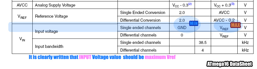
REFS1 REFS0 selects the reference voltage. See table below –
| REFS1 | REFS0 | Voltage Reference Selection |
| 0 | 0 | ARef internal Vref Turned off |
| 0 | 1 | AVCC |
| 1 | 0 | Reserved |
| 1 | 1 | Internal 2.56 Voltage Reference |
ADMUX=(1<<REFS0);
The ADCSRA Register.
- ADEN – Set this to 1 to enable ADC
- ADSC – We need to set this to one whenever we need adc to do a conversion.
- ADIF – This is the interrupt bit this is set to
1 by the hardware when conversion is complete. So we can wait till conversion
is complete by polling this bit like
//Wait for conversion to complete
while(!(ADCSRA & (1<<ADIF)));
The loop does nothing while ADIF is set to 0, it exits as soon as ADIF is set to one, i.e. conversion is complete. - ADPS2-ADPS0 – These selects the Prescaler for ADC. As I said the ADC frequency must be between 50KHz to 200KHz.
 |
We need to select division factor so as to get a acceptable frequency from our 16Mhz clock. We select division factor as 128.So ADC clock frequency = 16000000/128 = 125000 = 125KHz (which is in range of 50KHz to 200KHz). So we set ADCSRA as
ADCSRA=(1<<ADEN)|(1<<ADPS2)|(ADPS1)|(ADPS0); //Enable ADC with Prescalar=Fcpu/128
Reading an analog value.
Now every thing is set up. We now write a routine that will ReadADC.
uint16_t ReadADC(uint8_t ch)
{
   //Select ADC Channel ch must be 0-7
   ch=ch&0b00000111;
   ADMUX|=ch;

   //Start Single conversion
   ADCSRA|=(1<<ADSC);

   //Wait for conversion to complete
   while(!(ADCSRA & (1<<ADIF)));

   //Clear ADIF by writing one to it
   ADCSRA|=(1<<ADIF);

   return(ADC);
}
Sample Code.
The following is complete code to Read Channel 0 and display its value on LCD.
#include <avr/io.h>

#include "lcd.h"

void InitADC()
{
ADMUX=(1<<REFS0);                         // For Aref=AVcc;
ADCSRA=(1<<ADEN)|(1<<ADPS2)|(1<<ADPS1)|(1<<ADPS0); //Rrescalar div factor =128
}

uint16_t ReadADC(uint8_t ch)
{
   //Select ADC Channel ch must be 0-7
   ch=ch&0b00000111;
   ADMUX|=ch;

   //Start Single conversion
   ADCSRA|=(1<<ADSC);

   //Wait for conversion to complete
   while(!(ADCSRA & (1<<ADIF)));

   //Clear ADIF by writing one to it
   //Note you may be wondering why we have write one to clear it
   //This is standard way of clearing bits in io as said in datasheets.
   //The code writes '1' but it result in setting bit to '0' !!!

   ADCSRA|=(1<<ADIF);

   return(ADC);
}

void Wait()
{
   uint8_t i;
   for(i=0;i<20;i++)
      _delay_loop_2(0);
}

void main()
{
   uint16_t adc_result;

   //Initialize LCD
   LCDInit(LS_BLINK|LS_ULINE);
   LCDClear();

   //Initialize ADC
   InitADC();

   //Put some intro text into LCD
   LCDWriteString("ADC Test");
   LCDWriteStringXY(0,1,"ADC=");

   while(1)
   {
      adc_result=ReadADC(0);           // Read Analog value from channel-0
      LCDWriteIntXY(4,1,adc_result,4); //Print the value in 4th column second line
      Wait();
   }
}
Hardware
 |
Fig: LDR Connected to ADC of AVR |
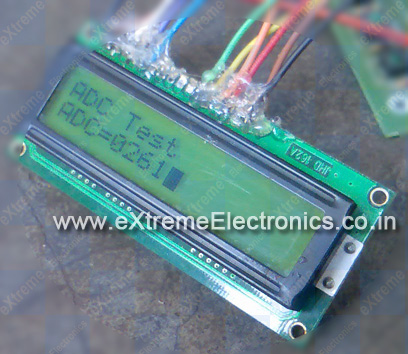 |
Fig: Screenshot of ADC Test App. |
Downloads
Note:- I used the xBoard for testing the application but you can use your own development board. See Home Made AVR Devboard.
- You can also get a low cost ATmega8 based board and “USB AVR Programmer” for quick start.
- For LCD Interfacing See- “LCD Interfacing Tutorial”
- Please Read the Tutorial “Internal Peripherals of AVR” before using ADC of AVRs.
More AVR ADC Applications
- Interfacing Temperature Sensor – LM35
- Interfacing MMA7260 Triple Axis Accelerometer with ATmega32
- AVR Graphic LCD and Accelerometer Demo
- Visualize ADC data on PC Screen using USART – AVR Project
 |
ADC Data On PC (Click to Read More …) |
Pingback: Interfacing Temperature Sensor with AVR Microcontrollers - LM35 | eXtreme Electronics
hi.please guide me that how to use 2 or more channel of atmega32 adc(porta.0 ..7) togher by bascom. thanks alot best regard
Is it possible to configure different pins with different reference voltages simultaneously?
For example, PA1 at 2.56V, PA2 at VCC, and PA3 at VREF?
Hi
Yes, you can define voltage reference at any time on A/D registers. First time you configure A/D voltage reference on AVCC pin and then read A/D conversion then you configure A/D voltage reference on AREF pin and again read A/D conversion and finally you may like to use inside voltage reference that you can define it on A/D register.
@Jhon
Actually there is only one ADC inside the chip and the Input to it is multiplexed. So setting of different reference voltage for individual pins is not possible. But you can set the Reference voltage of ADC to required before taking the input for the desired pin.
For example set
ref=2.56 before sampling PA1
ref=VCC before sampling PA2
and ref=VCC before sampling PA3
this should give you desired result.
Two more quick questions . . .
If I set the ref voltage to 2.56V, and send a 5V signal to that ADC pin, would it get damaged?
Some of the ATmega’s, such as the 2560, have two ADC ports (16 pins). Could the the reference voltage on each be set differently?
@Jhon
Ya than would damage the chip. With AVRs with two or more ADCs thats easily possible. Or if you want more ADCs you can go for separate ADC chips. Then you can design more complex circuit.
@Jhon
The following is an excerpt from data sheet
“If the user has a fixed voltage source connected to the AREF pin, the user may not use
the other reference voltage options in the application, as they will be shorted to the
external voltage. If no external voltage is applied to the AREF pin, the user may switch
between AVCC and 2.56V as reference selection. The first ADC conversion result after
switching reference voltage source may be inaccurate, and the user is advised to dis-
card this result.
”
So you can easily switch between internal reference of 2.56 and 5.00 volts. But if you also need a third i.e. Custom Voltage applied to Vref it is not possible unless you have more onchip/off chip ADCs
it means that only two ref voltages can be used either 2.56v or 5v ………..but what to do if we want any voltage other than those two …
@Raghu
“it means that only two ref voltages can be used either 2.56v or 5v ………..but what to do if we want any voltage other than those two …”
its simple , see the table in ADMUX register description above . In this example we have gone for 2nd option (bold italics) but to use any other volatge go for first option. Then you can apply any voltage to Aref pin (its pin 21 on mega8) and it will be the reference voltage.
Hope you got it!
Hi,
can you pls provide the asm code to this program.Thanks alot
Can I use 2 multiplexer pins for ADC Analog Compare and rest for Input?……
Pingback: Reading Temperature Sensor from STK500 « Home Commander
Hi Avinash,
your tutorials are very helpful especially for newbies,my question is how can use your adc test for two channels.What i want to do is to measure voltages from two adc channels say 0 & 1 and display the result on the LCD.
Thank you.
@Adeola,
I think that is very easy once you understand the above code.
how to write as sembly language program in 8051 in order to make a light adc involving sensor an lcd?
HI
I like your tutorial,but i have one question i.e. how to use assembly language rather than c.
Thank you
Hi Avinash,
I am reading voltage from six adc channels of atmega32 in round-robin fashion and displaying the voltage on LCD. But I am getting different voltage of all channels in diferent round means I am not getting constant voltage in different rounds. With Voltmeter I checked the voltage at microcontroller pins, it is constant. I am feeding Unity gain opamp output to ADC inputs.
Please tell me the solution.
Hello Sandeep,
U r usin 6 ADC ch then r u using the other 2 Pins of PORTA for any digital IO (like Interface to LCD?).
If thats the case then free those PINs
Also let me see the code and schematic
mail them to me@avinashgupta.com
Dear Avinash,
I have sent the required information on urs email (me@avinashgupta.com). Plz tell me the solution.
hello….if the vref=2.5 and the input voltage is 3vol..then the how much ‘ll b the decimal value in ADCH
@santosh
hi everybody.
i have no good knowledge about ADC conversion. at my projects i just can use only 1 channel ADC on ATmega32, but actually i want to use 4 channel ADC in the same time. please help me how to use 4 channel ADC?
Sorry made a mistake in the comment that i use a following problem
it is I use the following program and problem is unit digit fluctuation please help me to make ADC reading stable on the seven segment display
Para leer de ADC0 a ADC7 cambia esto:
__###################__
/* ch=ch&0b00000111;
ADMUX|=ch; */ <—– Error
__###################__
Por esto:
__###################__
ch=ch&0x07;
ADMUX = (ADMUX&0xF8)|ch;
__###################__
Thank you snowserf.
Your comment was very help for me.
Hello i´m making a voltmeter with assembler, my question is if i want to send to the lcd the value of the voltage instead of the binary number what do i have to do?
I think i have to compare the result of the ADC and then assigned the value that i want in the LCD but i have to compare several values and i think i lost time comparing , or what do you think?
Conver the binary no to a string say if ADC read out is 792 (stored in int) break it to ‘7’, ‘9’, ‘2’ ij ASCII and sent to LCD
The algo would be
int a;
a=ReadADC();
while(a)
{
char ch;
ch=a%10; // divide by 10 and strore remainder in ch, 792%10=2 so u get the last digit
ch=ch=10; // remove last digit, 792/10= 79
}
Hello Avinash!
Great tutorials! A question regarding “Fig: LDR Connected to ADC of AVR”. What I see there is 100 kohm resitor going to ground. Is that a standard resitor value for all types of ADC connections? I have seen 10 kohm resitor values as well in schematics. What I try to say is: should it always be a resistor placed (to ground) like that when using AVR adc?
Regards
Johan
@Johan
Here LDR and R(100K) froms a Voltage Divider. More info here http://en.wikipedia.org/wiki/Voltage_divider
@Johan
here LDR is changing resistance according to light but ADC can measure Voltage only. To convert RESISTANCE to VOLTAGE we have used a Voltage Divider.
hi avinash
my question is how to get ADC from multiple channels simultaneously.i used to get but the result of all the channel was same .
thanks for your help
i am connecting a LDR to a PIC. i want to compare the value that the LDR to the preset value. how do i represent this preset value in hex? for example, if the value of LDR is less than 3V, then do the following commands. how to concert the 3V to hex value? thanks.
@Jing
3v is 60% of 5v (Ref Voltage) so 60% of 1024 (Max Value for 10BIT A/D) is required value. 60% of 1024 is 614.4 = 614 and its HEX equivalent is 266. You must write 0x266 (prefix by 0x) in ‘C’ so that compiler knows it is a HEX and not decimal.
Hey Avinash,
Where do you buy all your electronics stuff in India? I live near Dehradun and for me it seems impossible to get any stuff, no hobby shops around!! Is there any safe online shop which deals with it and do you know any place around Delhi or preferably Lucknow?
I was able to get in touch with ATmega16 there in Lucknow for my surprise!! :p
Hello Pranav,
Many people in India face same problem. Thats why I started a Online Shop. You can visit it here
http://shop.extremeelectronics.co.in/
I was very angry by local dealers not giving correct parts and also charge so high.
hi pranav,
U better visit delhi,s lajpat rai market for required stuff ass you can found every thing required there…and that cheaper then any where else u will get
Hi, I’ve build a filtering ciruit and attached it to the adc, connected to the adc is a resistor, on one side of this i’m getting 2.5v on the micro side im getting 0v. if I remove the micro, this goes up to 2.5v. The signal is at approx 0.2mA is this enough? What do i need to set the DDR to for the adc port? I want to use some of the other portbits as digital inputs. Thanks for any help!
hi avinash, good work.
hi i am very poor in basic electronics and also in practicle(circuit designing)….
hi can u sugest me some good websites that gives some idea on basics and circuit design..
Hi
l am just starting to work with atmega16 controller and got a hang first tutorials and desided to try this one to but then l connect everything together but then l start a program a result l get is always 1023 and l tryed hooking up a pontiometer insted a LRD and turning it but always l get only 1023 is there something l do wrong with my software? maybe with registers? l used exactly a same code as your posted in this tutorial and l got nothing. Connections is ok
@Andrew
Please disconnect everything from the ADC port. The value now should show random value. Now connect it directly to Vcc the value should be 1023 and then connect (ADC0) to the GND pin it should show 0.
yeah tryed it and then noticed some mistakes in a code l wrote it works nicely thx 🙂
i have gone through the program.its so simple and quickly understood, but only confusion is that which port is assigned to take output,and how to connect that port to LCD…?
@ABY
please see article on LCD interfacing first. their you will get details on lcd connections
Very nice tutorial!
I have one question, is it possible to use the other pins to other stuff (like lighting LEDs) if I only use one pin for the AD conversion? Or will the AD conversion use the whole port?
I use an AT Mega 16 and the port A is used for AD conversion as well. Can I use port A both to do AD conversion on pin 0 and light a LED on port 1?
Kind regards
@Samuel,
good question. I recommend using the other pins of ADC PORT as INPUT only. And use some other I/O port for OUTPUT purpose. Once I tried to do the same thing. One ADC was used as ANALOG IN while the other pins carried medium frequency DIGITAL OUTPUT signal (to switch seven segment displays). In this configuration the ADC result were not constant, it was fluctuating. When I made the other PINs of ADC free and used some other PORts the problem was solved!
🙂
So this info may be useful for you.
Your tutorial is just awsome!!I just want to know how to use two or more adc channels simulataneously.Old question asked so far.Bt pls hlp me out.thnx.
satyantan you just need to change the settings of ADMUX register for accessing different pins of ADC.Have a good look at the Data Sheet.
thanks for d tutorials… they were very helpful
the atmega32 i am using shows highly fluctuating values even when the input to the pin is constant… wht cud be the problem?
and can we read negative voltages using atmega32 adc?
im a little confused with the lines:
ch=ch&0b00000111;
ADMUX|=ch;
does this mean that you are asking it to perform ADC on the first three channels, although you only need it from channel 0 because this is where you are reading the result from, so it could really be ch=ch&0b00000001;? Or have I drastically misunderstood this? So if i wanted to read if from channel 7 i could put ch=ch&0b10000000; and then change the last part to adc_result=ReadADC(7);?
@Max
ch=ch&0b00000111;this line limits the channel number to a valid value. If you pass ch between 0-7 it remains unchanged but if you pass for example 11 it will be converted to 3. To get how it works you must be familiar with binary numbers and bit wise logical operation using bitwise logical operators like &.
ahh thanks, this has clarified things for me a lot, i understand now. Now i shall get to work on programming my line following robot!
my question is how to get ADC from multiple channels simultaneously.
i tried to edit sample code described above to such form:
.

.

.

while(1)

   {

      adc_result=ReadADC(0);           // Read Analog value from channel-0

      LCDWriteIntXY(4,1,adc_result,4); //Print the value in 4th column second line
Wait();
adc_result=ReadADC(1); // Read Analog value from channel-1
LCDWriteIntXY(10,1,adc_result,4); //Print the value in 10th column second line
}
.
.
.
but the result of all the channel was same .
@ Peter
ReadADC(0) just reads channel 0! The ADC can only do one conversion at one time (unless you’ve got a fancy chip with more than one ADC multiplexer on)
One way I did this was I wrote a conversion complete interrupt, which on conversion of a channel, stored it in to a variable (an array to be precise) and then started on the next conversion.
In the main loop, where ever I wanted to read more tha one ADC value, i just read the values out of the array, which were contstantly being updated by the interrupt! You can have my code if you like, just reply and let me know!
@ Phil:
Please can I have your code?
Multiple ADC Reading code can be found here
https://extremeelectronics.co.in/robotics/obstacle-avoiding-robot-using-avr-atmega32-%e2%80%93-part-ii/
Hey, where can u find the lcd.h file? I took it out of his lcd guide, but then I still get some errors like:
I:\Eli, Elo, TT,\GIP\SVEN\ldr\default/../ldr.c:45: undefined reference to `LCDInit’
I:\Eli, Elo, TT,\GIP\SVEN\ldr\default/../ldr.c:46: undefined reference to `LCDByte’
I:\Eli, Elo, TT,\GIP\SVEN\ldr\default/../ldr.c:52: undefined reference to `LCDWriteString’
I:\Eli, Elo, TT,\GIP\SVEN\ldr\default/../ldr.c:53: undefined reference to `LCDGotoXY’
I:\Eli, Elo, TT,\GIP\SVEN\ldr\default/../ldr.c:53: undefined reference to `LCDWriteString’
I:\Eli, Elo, TT,\GIP\SVEN\ldr\default/../ldr.c:58: undefined reference to `LCDGotoXY’
I:\Eli, Elo, TT,\GIP\SVEN\ldr\default/../ldr.c:58: undefined reference to `LCDWriteInt’
@Sven
Read the LCD Article CAREFULLY ! I think you are running too fast!
Hello Avinash,
your tutorials are really wonderful, they are very easy to understand and implement.
I want to read voltage values from 8 sensors using 8 adc channels on Atmega32 MC and then write these values to an SD card memory continuously, I have all the hardware required.
Can you suggest me an easy way to do this or do you have any tutorials related to this application. please help me out.
thanks.
@Hari
http://www.dharmanitech.com/2009/01/sd-card-interfacing-with-atmega8-fat32.html
I think this article will surely help you out!
Pingback: Interfacing MMA7260 Triple Axis Accelerometer with ATmega32 - AVR Tutorial | eXtreme Electronics
@Av
Hey Av.. any chance of putting a mapping function into the adc? These LSR’s have a wide range of resistance like from 0 – 200k +.
Youre doing a great job.
@Av
I have a great idea for a tutorial… sensors which output are measured by frequency. cool huh? :o)
@Wlevis,
Nice Idea, give me a example sensor and I will design code for it.
@Av.. about ADC.. how about a tutorial that does a 10bit conversion?
@Av..
To my knowledge, practically all the non-ic humidity sensors are frequency dependant devices
Hello,
The LDR tutorial is good and works well too, when I tried it out on the XBoard MINI. The 100K resistor measures low light (tubelight) accurately but is swamped when exposed to sunlight.
I have been told that using a 1K resistor will measure sunlight more accurately. Will there be any problems for the ADC if I were to use a 1K resistor. I am told that ADC can take a max of only 40 milliamps? Thanks.
Hi,
This tutorial is useful for me.But, I just want the ADC in 8 bit resolution. After that, the results of these 8 bit data need to send out through TXD.What should I write for the programming?
easy to understand, tks
hello
how can i obtain an analogue output from avr microcontroller thank you
You should use PWM and filter it through a capacitor. After few trials you should be able to produce any analog value up to 5V.
@Ahmad,
Use the technique called PWM
https://extremeelectronics.co.in/avr-tutorials/introduction-to-pwm-pulse-width-modulation/
How can I get the LCD to display the ADC value in percentage, i.e. 0 = 0% and 1024 = 100%. Any sample code would be greatly appreciated. Thanks!
@Chris ask any 5th standard student!
percent = (adc_input/1023)*100
thats it !
If you know arithmetic try putting 0 and 1023(max value adc can give ) in the above equation
Hi, I had some serious problems using this code for multiple inputs, but the following substitution fixed the error:
use:
ch=(ADMUX & 0xf0)|(ch& 0x0f);
ADMUX=ch;
instead of:
ch=ch&0b00000111;
ADMUX|=ch;
@Thomas H
Thanks for finding and fixing the bug!
Thanks a lot Thomas!
I had been troubled by the original channel selection code bug for 3 days…
Thanks! The solution seems to work just fine with multiple inputs.But the thing is I’m unable to find the difference between
ch=(ADMUX & 0xf0)|(ch& 0x0f); //Correct
ADMUX=ch;
(AND)
ch=ch&0b00000111; //Bug
ADMUX|=ch;
could you please elaborate.
Regards
Also Avinash kindly correct the bug in the original code to avoid misleading people.
Regards
Here’s the explanation:
Imagine you want to read from ADC1 (ch = 0b0001) and afterwards from ADC2 (ch = 0b0010). Because of the bug, 0b0010 would be ORred with the previous value of the MUX3:0 bits (0b0001) so the result would be 0b0011 (ADC3) instead of 0b0010 (ADC2). That’s why you first have to reset the lower 4 bits of the data held by the register (ADMUX&0b00001111) and only then OR with the channel selection value. ch&0b00001111 is as a precaution so ch greater than 15 wouldn’t touch the upper 4 bits of the ADMUX.
@Chupo_cro,
Thanks a lot for your time to post a useful comment 🙂
A correction:
Instead of:
That’s why you first have to reset the lower 4 bits of the data held by the register (ADMUX&0b00001111)…
there should be:
That’s why you first have to reset the lower 4 bits of the data held by the register (ADMUX&0b11110000)…
@Avinash:
You’re welcome 🙂
If you are able to edit the comments, you may edit my first comment (January 30, 2013 at 2:13 am) and correct the binary value according to the correction in my second comment (January 30, 2013 at 2:16 am). Then you may delete my second comment so it would be easier to read the discussion.
Regards
Thank you also Thomas, that was really annoying!
No problem! Glad to see my comment still helps people! Why not just fix the code on this page?
@thomas
Still unable to read multiple pins
i dont know were im going wrong….
wen i m reading individually everything is fine…
is there some something with the hardware
i m trying to read LM35,POT and LDR using same come as suggested Avinash and modified by u…
k…
i got it working the problem was with hardware
replaced it and its working nw…..
@Avinash, im not sure that that would work. If you divided by 1023, then the answer would be one as it cant deal with decimal fractions unless your using the float data type. If you only need 1% accuracy, why not grab the 7most significant bits from adc times by 100 and then divide by 127. That way you can advoid floats, and your code should be significantly faster (because your advoiding floats, and using smaller numbers!)
I apologize for my ignorance. I wasn’t asking for an arithmetic lesson, just help with the C code which I am a beginner. I was enjoying your website and tutorials until I was ridiculed. What’s the sense of publishing tutorials for beginners if you are clearly offended by a beginner’s questions. Phill, thanks for being open minded and not blinded by ego.
hi, thanks for the great tutorial…..it is really very helpful for beginners like me.
i had a doubt….in your ReadADC routine when you say :
ch=ch&0b00000111;
ADMUX|=ch;
we are also setting the REFS1 and REFS2 to 0…..which means we are no more using AVCC as our reference voltage(which we were supposed to do).
Please correct me if i am going wroing somewhere.
thanking you in advance.
Sorry for the question posted in my previous comment.
I didn’t noticed the bitwise operator ‘|’ in ADMUX|=ch;.
Anyway thanking you.
There is a function named LCDInit(LS_BLINK|LS_ULINE) in the code given above but, the actual name of the function in lcd.h supplied by your web-site in LCD usage tutorial has the function InitLCD(LS_BLINK|LS_ULINE).
Please consider changing this and make this to be in sync with that tutorial.
please provide some insight into use of ADC in differential mode and a sample code to assist beginners .
Hi, I’m having a problem regarding with getting the percentage of the adc reading. I am using this equation percent=(adc_result1*100)/1023. I get my percentages right, but the problem is that after 64 percent it jumps to 1 percent again, I was wondering if you could help me figure out the problem.
declare percent as float like
float percent;percent = (adc_result*100.00)/1023.00;
What changes do i need to make to print the decimal values also?
Pingback: LED with adjustable flash, need help
Pingback: Visualize ADC data on PC Screen using USART - AVR Project | eXtreme Electronics
Is there any way to test segment program without Microcontroller. I means that I wanna test segment code as a new programmer in my PC. Please reply to me…
thank u.it is a great tutorial.but i have a question if instead of using lcd we would like to the accelerometer values in eeprom of atmega128,then what do we need to do?
Its really a nice tutorial for new guys in avr!!!
Its really a nice tutorial for new guys in avr!!!
thanx dear.!!
Hello.I have a problem understanding this line of code:
ADMUX=(1<<REFS0);
I know that "<<" is the bitshift operator. The operation x<<n shifts the value of x left by n bits. If REFS0 is initial 0 then 1 is shifted to the left by 0 positions. So in the right-hand side we have the bit value 1 and this value is assign to ADMUX(a register with 8 bits).Is this possible? I'll appreciate if you could help me figure out this problem.
Thanks.
@Mike
see this
https://extremeelectronics.co.in/avr-tutorials/programming-in-c-tips-for-embedded-development/
Hi,
Just wanted to point out that ADCSRA should be set as:
ADCSRA=(1<<ADEN)|(1<<ADPS2)|(1<<ADPS1)|(1<<ADPS0); //Enable ADC with Prescalar=Fcpu/128
You did not shift 1 by ADPS1 and ADPS0 in the explanation while it is written correctly in the code.
Hope I'm not wrong…
Sir thank you very much for your great support through these tutorials.Please post tutorials on arduino development boards.
I hope that in future Arduino Uno will be there in your online shop.
Thank you.
@Abhilash
Thanks, but I personally don’t like Arduinos. So I am never gonna work on those.
Hi Avinash & thanks for this wonderful page of AVR. I have a question friend. where returns the function return(ADC)? thanks
these tutorials are great. you are great.
i will be very happy if you add one tutorial for me
how to convert 8bit and 16bit adc value to seven segment
desplay.
or make a complete programe 0 to 30volt 4digit volt-meter.i shall be very thankfull to you.
thanks
mr.rizwan ahmed.
2.04.2012 12pm
Thanks! This is an excelent and easy tutorial to follow. The example program worked first time also. Very inspiring.
hello!
i have to do 16 to 16 bit multipication in atmega32 bt i am nt getting a right code…..
plz can u help in getting code?
I need a little explaination
//Wait for conversion to complete
while(!(ADCSRA & (1<<ADIF)));
what we are exactly doing by this !ADCSRA&(1<<ADIF)
//Clear ADIF by writing one to it
ADCSRA|=(1<<ADIF);
why we are doing this as it is done by the hardware in the previous code….
its a confusing or m nt getting the concept correctly???
what is the function of
void Wait()
{
uint8_t i;
for(i=0;i<20;i++)
_delay_loop_2(0);
}
What is the material that is used for binding the wires to the LCD display? I have soldered pins to the LCD display…this looks like something else…is it suitable replacement for soldering, where heating the element is not permitted ?
Here normal soldering is used . But over the soldering ,hot glue is used to protect the wires from braking.
line follower program for analog inputs to mcu ….thanks in advance
Pingback: Interfacing Analog Joystick with AVR ATmega32 | eXtreme Electronics
Hello! I used lm35 and displayed its temperature on bargraph led but the value always keeps varying.
#define F_CPU 4000000UL
#include
#include
#include
int main()
{
DDRA=0b01111111;
DDRB=0xFF; // bargraph led
PORTB=0;
ADCSRA = 0b10001111; // ADC+interrupt enabled,1:128 prescaler
ADMUX = 0b11100000; // 2.56V ref,left adjusted data
sei();
ADCSRA|=(1<<ADSC);
while(1);
return 0;
}
ISR(ADC_vect)
{
cli();
PORTB=(ADCH);
_delay_ms(2000);
sei();
ADCSRA|=(1<<ADSC);
}
Dear avinash,
can you make me understand why we are doing this ch=ch&0b00000111;
ADMUX|=ch;
?
i am a beginner,need help! please guide.
thanks in advance.
@Masterofdisguise
You need to be “master” of bitwise operator, numbering system and patience to read in order to understand that!
So do you know the following?
1)operator &
2)operator |
@avinash:
sorry for the late reply.. yeah i do understand the operators & and |.These are bitwise and or operators.Actually i understand c but embedded c appears to be bit different may be i m new to this field that’s why?.I want to know why are we masking,the lower order bits for the variable ch(I mean making them one). And how the ADC register ADMUX is able to select the input channel.
sir I used your lcd lib code (that is lcd.c,lcd.h and myutils) with atmega48 to write code on temperature monitor and switch relay connected in portd as well display the value in lcd. the code works very well but my problem is the relay is not switching at any value of adc i want it to switch. so my question is did you use portd in your lcd lib code or the lcd lib code is not for atmega48. please how do I solve this problem
Good effort its helps a lot to start ADC….
how to take multiple ADC readings from PA0 & PA1. is that setting ADMUX registor to corresponding bits in each function is enough for taking continuous reading ?
Dear Avinash,
How to display float value of mathematically manipulated ADC value on LCD?
@Yogesh,
Use your right brain, take some help from the left part too. Then think of what is a LCD and what it shows, then think what is float. Then prepare an algorithm to solve this problem. Then try to bring to life the concept from your brain to this physical world. If it doesn’t work, try to collect the inputs and use them as a feedback to correct the first. Repeat the process until you die or get the solution. Contact me when you have at-least repeated the loop 10 times without success. Understood?
Hi,
I am connecting LM35 temperature sensor with ATMEGA328. I have connected it to ADC5 and VCC and GND.
My question is that do i need to pass voltage to AVCC or AHREF in order to use ADC ?
Also, if i dont pass voltage to AVCC and AHREF, will i get ADC sensor values ?
Thanks,
Ujjwal Soni
@Ujjwal Soni,
Read the data sheet of ATmega328
What if i want to display the adc value as a float type like adc/12.5 = 1023/12.5= 81.84 on lcd display.
What would be the code for this purpose???i have tried this code
adc_result=ReadADC(0)/204.6;
sprintf(lcd,”%0.2f”,adc_result);
LCDWriteStringXY(0,0,lcd);
lcd buffer has been also declared before.But the code doesn’t work.Shows garbage data on lcd.Please give a valuable advise of yours.Thanks in advance.
@Mahmud your process is correct, but avr-gcc has three flavous of sprintf. You need to link against floating point version. avr-gcc manual clearly state this.
Try this
int adc_result,adc_result_q,adc_result_r;
adc_result = ReadADC(0);
adc_result_q =(adc_result*2046)/10;
adc_result_q =(adc_result*2046)%10;
sprintf(lcd,”%d.%d”,adc_result_q,adc_result_r);
LCDWriteStringXY(0,0,lcd);
########TRY THIS##########
int adc_result,adc_result_q,adc_result_r;
adc_result = ReadADC(0);
adc_result_q =(adc_result*2046)/10;
adc_result_r =(adc_result*2046)%10;
sprintf(lcd,”%d.%d”,adc_result_q,adc_result_r);
LCDWriteStringXY(0,0,lcd);
Hey @Gangster,
Thanks man. but i have solve the problem.any ways Thanks again for ur code.
mahmud,i m facing the same problem.can u please tell how u corrected it??
Pingback: Getting Started with Microcontrollers | eXtreme ElectronicseXtreme Electronics
sir, I am working on ATtiny87. I just want to know the uart communication on that can you help me please…
@Sumita,
have you used USART before?
hiii Avinash nice tutorials..ive bought avr programmer+dev board from extreme electronics recently…i must say you have done a grt work here
Hi Im chandra , i need the atmega8 c code for adc with uart .
convert analog to digital and sent to uart port .
chnadra.sreekala@gmail.com this is my email id sent to email …
sir i have found a mistake in your ReadADC() function.
suppose i want to first read ADC channel 1 and then read ADC channel 2.
so when i write ReadADC(1);
so ADMUX will be 0b01000001
now if i write ReadADC(2);
ADMUX |=ch;
as u have done OR operation
so ADMUX=ADMUX | ch;
so ADMUX=0b01000001 | 0b00000010;
so ADMUX=0b01000011;
so ADMUX will read Channel 3 not Channel 2;
So i think OR operation is wrong here.
this is a simple program for adc which i have written,working perfectly with atmega16,but when i write the same for atmega8 it doesn’t work…
#include
#define F_CPU 16000000UL
#include
int main()
{
DDRD=0xFF;
PORTD=0×00;
ADMUX=(1<<REFS0);
ADCSRA=(1<<ADEN)|(1<<ADPS2)|(1<<ADPS1)|(1<<ADPS0);
while(1)
{
ADCSRA|=(1<<ADSC);
while(!(ADCSRA & (1<<ADIF)));
ADCSRA|=(1<<ADIF);
PORTD=ADCW;
_delay_ms(50);
}
}
plz..tell me ,what are the changes needed to be made ???
Dear Sir
Can I get a Weighing Scale 30kg 1g accuracy based on AVR. I need technical details tutorial with it.
Regards
George KUWAIT
Dear George,
You cannot get that resolution over the whole range. If you use a 10 bit ADC you have 2^10=1024 different values. The resolution and accuracy depend on the measuring hardware and the signal conditioning before it reaches the ADC on the AVR.
I think a scale is unlikely to be 1g accurate in the 30kg range, because of the typical quality of sensors. Even if you average out many values, the measurement might not be repeatable, i.e. have low precision.
See this for precision, accuracy, and resolution: http://www.tutelman.com/golf/measure/precision.php
Sir,
using your codes I’ve read many sensors but this time something wrong. I’m working on At-8, two ADC channel using. While I change the value of 5th ADC channel the value of 4th channel is automatically changed, and no vice-versa means there is no change by 4th even not in 4th output. Hardware is correct. What will be the reason . I’ve applied delay.
thanks for this tutorial..
am a newbie to avr..i have done this program with the same code but the value displayed in tha adc is always the same value ‘1023’..please help me..
and am using protues to stimulate this program.
hi
could u please describe me more, how LRD works in this project?
Hi sir,
i recently wrote a program for atmega8,iam getting
0-255 values,how to have 10 bit i.e.,1024 readings…
what should i be doing for that….
Hi there,
At lower temperature range especially for negative temperature mine adc value toggles around 2 to 3 degrees.Can anyone help me understand what exactly is going wrong.
hai,
I am connecting 2 ldrs to two adc pins,and want to compare the output power of two ldrs.so how should i go with it?
as far as i know the ports read voltage/current of the ldrs.so how do I make it read the resistance and estimate their power?
Hi Chet,
The short answer is: No, you don’t want to do that. 😉 What is the purpose?
The analog pins only measure voltage relative to the reference voltage, not current. Google ADC. To measure a varying voltage due to the LDR, google for example Arduino LDR. You would need a voltage divider or other circuit.
To measure the current you would need a circuit that converts the current into voltage and amplifies it suitably. Depends on your application. LDRs don’t generate current by themselves! See http://www.electronics-tutorials.ws/io/io_4.html
If you really want to measure power you can for example measure the resistance of the LDR using a multimeter under different lighting conditions and under those same conditions you measure your analog input value from a voltage divider. Tabulate those for approximations. Then you know voltage and resistance and can calculate power. Don’t expect to get accurate measurements unless you do it properly (which is too much to explain here).
BR, Thomas H.
hi avinash,
can you tell me what is the maximum input current one can give to adc pin of atmega 16,
and tell the method of scaling down the current of 2amps to the current that can be given as input to adc input of atmega16.
plz help me with this
Hi Dheeraj,
I think you have misunderstood the relationship between voltage, current and resistance. Read up.
The ADC has very high input impedance (resistance), maybe on the order of 100 megaohms, and the current draw of the analog pin will be on the order of nanoamps (ideally 0). The ADC measures voltage, not current.
If you need to measure current you can for example use a shunt resistor or other circuitry. Try googling that. If the shunt resistance is too high you will affect the operation of the circuit.
BR,
Thomas H.
ADCs measure voltage NOT current! If you want to measure current then you first need to convert it to voltage.
As Thomas H said ADCs and anyother voltage measuring device have very high input impedance and this is taught in class 12 physics.
Hi Avinash
please help me
I can not set the rejister adc i want to start adc in timer0 and stop the adc in inttrupt adc and then read adc so store the array . i dont no please help!!!!
EXcuse me sir!!!
I dont have facebook so i cant downloade sample code for adc .i need for help you.
thanks alot
Hello Avinash,
Can you please help me with the same concept where we can use LCD display instead of 7 segment display?
Hi,
Firstly, thank you for an excellent tutorial.
it was of great help in understanding the basics of ADC.
I also need to understand differential adc and how to use gain of adc in atmega 16.
however with almost nothing on the web explaining it,
it is getting really difficult.
it would be of great help if u make a tutorial explaining this.
Thank you.
hi sir.can you help me how to calculate frequency by adc unit of atmega32 ??do you khnow any source about it??I write and debug a schematic and program in code vision to calculate and show voltage of an analog signal but I want to add a part to my program to calculate frequency of signal and show it.thanks alot
i want read 8 input channel to the avr 164a program.
I have a problem with STK600 ATMEGA2560 and board A08-0431.A
I need to change the reference voltage for the ADC I need 2.56 and 1.1 the one after the other. When I change it it seems that the 1.1V is never applied. I tried to insert delay between these two succesive measurements and after 2s of delay the 1.1V finally was the reference for my ADC. Does anybody else experienced such a problem?
Hi,
This is really nice tutorial for beginners like me.
Just a small spelling mistake in below line:
“If an electrical quantity is made to vary directly in proportion to this value (temperature etc) then what we have is Analogue signal.”
Please change “Analogue signal” to “analog signal”.
Actually I have bought the 40 pin avr development board from extreme Electronics store. But I am not getting any reading from the lm35 sensor.Is your development board is suitable for adc conversion or not!? Or I have to make external connection for this AREF pin. .
@Deepam Das,
You you are unable to make this. Please send the board to us. We will make all connection and load suitable program and send it back to you. The cost would be Rs. 3500
I couldn’t get you. Why i have to pay Rs. 3500? I just want to know whether the Aref pin in the development board should be left disconnected or connected to ground or Vcc through ceramic capacitor.
It should be left unconnected.
Thanks u so much…….
it work for 10bits adc?
Yes, the AVR’s have 10 bit ADCs only
I am not value of adc upto 1023 on my lcd using 10 bit adc in avr.I only get value upto 200.why?
I AM IN KUWAIT. HOW I CAN ORDER YOUR PRODUCTS.CAN YOU ACCEPT PAYPAL.
hi
i have assignment which about (analog to digital conversion ) in ATmega2560
please can you help me with my assignment
How can we use adc value for delay?
Please help me/response.