Category Archives: Code Snippets

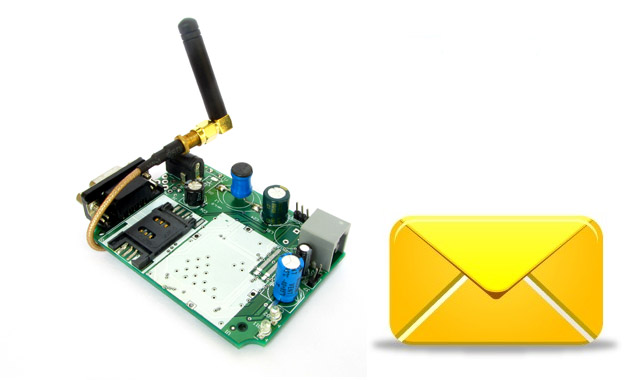
Sending and Receiving SMS using SIM300 GSM Module

If you want a live demo of this, please register from the link given below. (Only in Pune) REGISTER NOW! This project can also be implemented using a PIC18F4520 microcontroller. We have schematic and C library available. Hi friends in this part we will have a look at the functions related to text messages. By the end of this article you will have a clear idea of how to wait for a text message, read the message, send a new text message and deleted a received message. We have already discussed the basics of SIM300 GSM Module interface with AVR MCU in our previous tutorial you can refer that article to know about the schematic and basic communication code. GSM Module SIM300 Interface with AVR After reading the above article you will know how we have connected the SIM300, AVR ATmega32 and LCD Module to make a basic test rig. Also covered in the article is the detail about the communication method between SIM300 and AVR which is called asynchronous serial communication, done using AVR’s USART peripheral. The article shows you how to use the AVR USART library to send and receive data to/from the GSM Module. We have also discussed the command response method used for the interfacing with the module. Working code is provided that shows you how […]

Time Input Dialog for Graphic LCD

GUI Frameworks of all modern OS like Windows, Linux (Qt & GTK+), MAC etc have a concept of standard dialogs. For example all applications running under Windows shows the same file open dialog for selecting a file. Similarly their are standard dialogs for folder selection, colour selection, font selection etc. This concept has several advantages, and the most important is a easy user interface. Since the user is already familiar with file selection in one application, he/she can use file open dialog of any application. Building on the same concept our GUI framework for ProGFX (avr glcd driver) will too have many standard dialogs for common user interface. In this tutorial we will build the "Time Input Dialog" that helps programmer ask the user to input time. The time could be anything like :- "On" or "Off" time for a relay in a timer application. Alarm time in an alarm clock application. Period start time in a school bell application. And many others. The programmer just need to call the function. void ShowGetTimeDlg(uint8_t *h,uint8_t *m,uint8_t *s,uint8_t *am_pm) It takes four parameters hour, minutes, second and am_pm. All parameters are passed by reference(pointer actually), this is because the function modifies the value of those variables. It shows a dialog as shown below :- Time Input Dialog The user can use the […]

DS1307 I2C RTCC Interface using SoftI2C lib

In the last tutorial, I explained you how to use our SoftI2C library to read and write a 24CXX series I2C EEPROM. Now I will continue our exploration and write a register access layer for the DS1307 chip. The DS1307 chip is a real time clock and calendar IC. The register access layer that we will develop provides the application programmer with function that reads and write the registers of DS1307. Remember that any piece of hardware appears to the CPU as a set of registers only. DS1307 has :- Seven Registers (from 0x00 to 0x06) that are used for timekeeping functions. One CONTROL register(0x07) for square wave generation setting (we don’t use this for simplicity). 56 bytes of battery backup RAM (from 0x08 to 0x3F) Fig. : A Simple DS1307 RTC Module.   Once the application programmer has access to functions that reads and writes to any register (specified by its address) inside DS1307 ic, he/she can easily get and set the time infos like sec,min,hour, am/pm, date,month,year etc. The register access layer is built over the core Soft I2C layer. The register access layer consists of the following three functions. void DS1307Init(void) { SoftI2CInit(); } /*************************************************** Function To Read Internal Registers of DS1307 ——————————————— address : Address of the register data: value of register is copied to this. […]

24C1024 I2C EEPROM 128KB

24CXX I2C EEPROM Interface using SoftI2C lib

In this tutorial I will show you how to use our easy to use open source Soft I2C library to access a 24C64 EEPROM chip. We discussed the library in our previous tutorial. The functions developed in this tutorial will use services of the I2C library to read and write the EEPROM. The EEPROM access mainly contains only two routines. BOOL EEWriteByte(uint16_t address,uint8_t data); BOOL EEReadByte(uint16_t address ,uint8_t* data); The first one write a 8 bit data to a memory location specified by the variable address, since a EEPROM can have more that 256 bytes of storage that is why the address variable is 16 bit. The second function reads the memory location specified by the variable address and stores the read data in variable data. Both the function return EE_SUCCESS on success and EE_IO_ERROR on failure. How to develop the EEPROM Write function? We open the datasheet of 24C64A (64kbit) EEPROM and try to understand the random read and random write function. The figure 8 on page number 11 clearly describes the write steps. You just need to translate the figure into proper call to our Soft I2C lib API’s. BOOL EEWriteByte(uint16_t address,uint8_t data) { SoftI2CStart(); //SLA+W if(!SoftI2CWriteByte(EEPROM_WRITE_ADDRESS)) { SoftI2CStop(); //I2C i/o error return EE_IO_ERROR; } //Address HIGH if(!SoftI2CWriteByte(address>>8)) { SoftI2CStop(); //I2C i/o error return EE_IO_ERROR; } //Address LOW […]

Using Shift Registers with AVR Micro – AVR Tutorial

Today I am going to explain a helpful technique used while designing embedded system. The technique is to expand the number of input and output lines available in any microcontroller. The idea is to use a shift register, a shift register help us load data in a serial fashion (requiring less number of i/o lines) and then convert the data into a parallel form that can drive many types of load like LED,Relays, motor etc, just like normal i/o ports of MCU. Their are two advantage of this method:- Only three i/o lines can drive virtually any number of output ports. Say if you want to control 50 leds that are at the distance of 2 meter from the controller then you save lots of wires! and mess up too! The above described what we called an output shift register. Another type is an input shift register. This type is used to take input. It does reverse of the output shift register. It takes parallel input and transfer it serially to the MCU. The most common commercial example I found is the NES joystick. Their are 8 buttons (you will notice 10 but 2 of it are turbo, that means they repeat action A or B(turbo A or B pressed) at particular frequency when kept depressed) The designers didn’t ran […]

Multiplexed Seven Segment Display using PIC16F877A and HI-TECH C

#include <htc.h> #define _XTAL_FREQ 20000000UL typedef unsigned char UINT8; typedef signed char INT8; typedef unsigned int UINT16; typedef signed int INT16; //Connection of Seven segment display #define SEVEN_SEGMENT_LAT PORTD #define SEVEN_SEGMENT_TRIS TRISD //MUX Control #define MUX_PORT PORTB #define MUX_START_POS 1 //From which bit on port the select lines start //MUX settings #define MUX_DISP_COUNT 4 //Number of displays //Global Varriable UINT8 DisplayArray[MUX_DISP_COUNT];//Holds ‘data’ for each disp void SevenSegmentWrite(UINT16 n) { /* n=data to dislay example: n=1234 will display 1234 in a 4 segment display Working: This function breaks apart a given integer into separete digits and writes them to the display array i.e. digits[] */ UINT8 i=0; UINT8 j; while(n) { DisplayArray[i]=n%10; i++; if(i==MUX_DISP_COUNT) break; //We don’t have room for more digits n=n/10; } //Fill Unused area with 0 for(j=i;j<MUX_DISP_COUNT;j++) DisplayArray[j]=0; } void WriteSegment(UINT8 num) { switch (num) { case 0: //-GFEDCBA SEVEN_SEGMENT_LAT = 0B01000000; break; case 1: //-GFEDCBA SEVEN_SEGMENT_LAT = 0B01111001; break; case 2: //-GFEDCBA SEVEN_SEGMENT_LAT = 0B00100100; break; case 3: //-GFEDCBA SEVEN_SEGMENT_LAT = 0B00110000; break; case 4: //-GFEDCBA SEVEN_SEGMENT_LAT = 0B00011001; break; case 5: //-GFEDCBA SEVEN_SEGMENT_LAT = 0B00010010; break; case 6: //-GFEDCBA SEVEN_SEGMENT_LAT = 0B00000010; break; case 7: //-GFEDCBA SEVEN_SEGMENT_LAT = 0B01111000; break; case 8: //-GFEDCBA SEVEN_SEGMENT_LAT = 0B00000000; break; case 9: //-GFEDCBA SEVEN_SEGMENT_LAT = 0B00010000; break; } } void Wait() { UINT8 i; for(i=0;i<1;i++) __delay_ms(10); } void main() […]

Interfacing 12 bit SPI ADC (MCP3204) with AVR Micro

Hello All, Sometimes the Internal ADC is not enough. Like when you need more resolution or high speed. The internal ADC of AVR generally has the following specifications. 15K samples per second 10 bit resolution. If you need more than that you need an external ADC. You may also need external ADCs if you have already used the internal ones. This tutorial will guide you how to install an external ADC with AVR MCU and write a test program to get data from it. A very common external ADC is from Microchip the MCP3204. It has the following configuration. 100K samples per second. (More than 6 times faster than AVRs inbuilt) 12 bit resolution (4 times more detailed) 4 input channels (MCP3208 has 8 channels). SPI Bus Compatible. Basic SPI Tutorial These ADCs are SPI Bus based which is a serial bus. So the number of pins in IC is very low. Total of 4 lines are required to interface it with AVR MCU. MISO (Master In Slave Out) MOSI (Master Out Slave In) SCK (Serial Clock) CS (Chip Select) As you know in synchronous serial communication their is a clock line (SCK in case of SPI) which synchronizes the transfer. Please read the article :- Synchronous Serial Communication Tutorial – The Basics of I2C and SPI. The clock is […]

Sound Generation by AVR Micro – Tutorial I

Many project requires some kind of Audio output. For example a burglar alarm, an automated school bell or simple electronic games or even a robot! In Old days we used some some dedicated Music and Audio Effect chip to do that. At that time ICs such as UM66 were very popular. Now in the days of microcontrollers, a good design is to use least number of external components to get the job done. So if you still use external audio ICs with a MCU based design then your design is inefficient and costly. The smart idea is to get most of the job done in software. In this article we will learn step by step how to produce different kinds of audio effect by just using an AVR MCU and A speaker. After reading this you would be able to provide simple sound output in many AVR based projects. So lets get started! I will start this series with a direct runnable example so that you can burn it into an AVR and see how it sounds! In latter parts I will elaborate how this was achieved. Some techniques that were used to achieve audio generation are. PWM or Pulse width modulation: It is a technique to generate analog voltage levels by a digital device (say a MCU). Generally a […]

Easy 24C I2C Serial EEPROM Interfacing with AVR Microcontrollers

In this turorial we will see how we can easily interface a 24C series serial EEPROM with AVR microcontrollers. What is an EEPROM? An EEPROM is kinds of novalatile memory, that means it is used for storing digital data permanently without any power suply. EEPROM stands for Electrically Erasable Programmable Read Only Memory. The advantage of these kind of ROMs is that they can be erased Electrically to make them ready for storing new data. Compare this with a CD R disks they can be recorded only once. A small amount of EEPROM is also available internally on the AVR chips. So if the volume of data you want to store is small (say few user names and password) then you can use it. The internal eeprom makes design small and simple. But if the amount of data you want to store is large, say in order of few tens of kilobytes then you have to interface a External EEPROM chip with your AVR MCU. You can store pictures, sound and long texts in these eeproms. Their are many kinds of EEPROM chip available from many manufactures. One very common family is 24C series serial EEPROMs. They are available upto 128KB in size. They uses I2C interface with host controller (MCU) which is a very popular serial communication standard. I […]

PWM Signal Generation by Using AVR Timers. Part II

In this tutorial we will set up the TIMER0 in fast pwm mode and use it to generate PWM signals of varying duty cycles. In this way we would be generating analog signals of voltages between 0 and 5v. In the example we will connect this output to a LED and see how it varies its brightness. Please see the previous tutorials on PWM and TIMERs before reading this tutorial. PWM Introduction to PWM – Pulse Width Modulation PWM Signal Generation with AVR Timers. Timers Introduction To AVR Timers. Timers In Compare Mode Part I Timers In Compare Mode Part II Setting Up TIMER0 in Fast PWM mode Setting up the TIMER0 in fast pwm mode is very easy and just require one line of code. You only need to deal with one register named TCCR0 (Timer Counter Control Register For Timer 0). You just need to set up various bits in it to get the required setting. The various bits of TCCR0 is given below. TCCR0 This register is used for configuring the TIMER0. See Timer Tutorial for more info. The explanation of various bits of this register is as follows. Bit No 7 6 5 4 3 2 1 0 Name FOC0 WGM00 COM01 COM00 WGM01 CS02 CS01 CS00 Initial Val 0 0 1 0 0 0 0 […]