Category Archives: PIC Development Board

Making A Thermometer with PIC16F877A

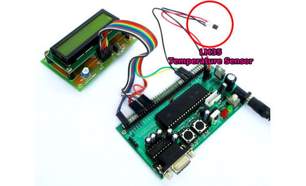
At basic level on microcontroller you can create this interesting project of digital thermometer. It teaches you how to acquire analog data from a sensor and display it on a lcd. We will use a popular MCU PIC16F877A to implement this mini project. The temperature will be read using a LM35 precision sensor. Final result will be shown on a 16×2 alphanumeric lcd module. Fig. PIC16F877A Based Thermometer with LCD   Stuffs Required S. No. Item Image Cost 1 40 PIN PIC Development Board Rs. 769 2 16×2 LCD Board Rs. 296 3 Single PIN Burg Wires Female/Female 20 units Rs. 100 4 12V 1A DC Adapter Rs. 127 5 LM35 Rs. 60     Total Rs. 1,352 Connections The PIC16F877A development board has the PIC16F877A microcontroller chip and its supporting basic circuitry all in a nice high quality PCB. The development board comes fully assembled and tested, thus makes it ideal for doing experiments for learning by beginners. 40 PIN PIC Development Board In the bottom portion of the pic development board you can see a row of male headers. Most of these pins are the microcontrollers general purpose input/output lines and the rest are 5v and GND supply lines. Using these pins you can connect external peripherals (like the LCD board or something else) to do your experiment. […]

Making “The LCD Expansion Board” for PIC18F4520

In this tutorial I you show you how to make a very useful expansion board for our PIC development board. It will be a Do It Your self (DIY) LCD Expansion board. The expansion board can be plugged into the PIC development board to add 16×2 Alphanumeric LCD Support to it. Since LCDs are required in many projects and experiments it will be a very helpful board. I recommend you to read the LCD Interfacing Tutorial before you proceed. It will give you an Idea how LCD is connected to PIC Microcontrollers. So lets start! Schematic for LCD Expansion Board. Fig.: LCD Module Interface with PIC Microcontroller. The board is very easy to make as the MCU core unit is already done for you. So you need to just care about the LCD part. It consists of the 16×2 LCD Module and A variable resistor (10K) only! Optionally you can add a 47ohm series resistor with the LED backlight of the LCD Module, to enable the backlight. The variable resistor is used to adjust the contrast of the module. If NO text is displayed adjust this pot. All I/O ports and power supply is available at the top of expansion board. Fig.: A blank expansion. As you can see the top row in the board lists all I/O port of […]

PIC Development Board – Expansion of Board

The PIC Development board from eXtreme Electronics has the feature of connecting add-on boards, like user interface board or a motor controller board. You can also make your own expansion board. Actually the board has the ability to connect a prototyping area where you can create your project specific circuit while the "basic" environment for PIC resides on the Development board. Fig.: Replaceable Prototyping Area   In this way many project can be created and kept for future use. Each project resides in its own board when you need that simply pair it with development board and the project is up and running! No messy wiring! Preparing a Veroboard for connection Take a general purpose PCB (veroboard) and solder a 40 PIN right angled burg strip connector in one end. Fig.: Replaceable Prototyping Area Now the it is ready to plug into the Development Board. Fig.: Replaceable Prototyping Area   After you connect your prototyping area to the Dev Board all PORTs of PIC MCU and Power Supply becomes available in the veroboard. Here you can connect all sort of components required by your project. It is very easy to remove the prototyping are and replace it with a fresh new one for another project. Thus a single development board can be used for many different projects. The 40 PIN […]

PIC Development Board – Hello World Project

Hello friends, welcome to this exciting tutorial were we will begin our journey with latest PIC18F micros from Microchip Technologies. This tutorial will give you information on what software/hardware you will require and basic steps on how to get, install, configure and use them. After going through this tutorial you will have a complete setup and knowledge to experiment with these powerful chips !           What you will learn ? MPLab as a powerful IDE. HI-TECH C for PIC18 MCUs as a powerful C Compiler. Creating a new HI-TECH C project in MPLab. Write a C Code to blink LED and compile it to get a HEX code. Configure the MCU for proper oscillator selection. Basic Use for PIC development board from eXtreme Electronics Burn the HEX code to MCU using eXtreme Burner PIC from eXtreme Electronics. Use the programmed MCU to actually blink the LED ! So lets get started !!! First get these stuffs Microchip’s MPLab IDE or Integrated development Environment. This is the central tool from where you can access most of other tools, like the C Compiler. This also lets you create and edit program files and projects. Download this from Microchips Web site and Install it in your computer. Download MPLAB IDE Free. HI-TECH C Pro for PIC18 MCUs – This […]

PIC Development Board – Programming

The PIC Development Board can be easily programmed INCircuit by using our eXtreme Burner – PIC, a PIC Programmer with USB Connectivity. The firmware of a Microcontroller is normally stored in HEX files. This HEX file is generated by an assembler or a Compiler. In this section we will show you how you can transfer a HEX file from your PC to the Microcontroller. NOTE: It is assumed that eXtreme Burner – PIC (hardware) is installed as described in its documentation. It is assumed that eXtreme Burner – PIC (software) is installed as described in its documentation. Connect the PIC development board with the programmer using a six pin female to female cable as shown below. Power on both development board and the burner. Fig. Six pin female to female cable for ICSP.   Fig. 6 PIN ICSP of Development Board.   Fig. 6 PIN ICSP of eXtreme Burner – PIC. Launch eXtreme Burner – PIC from Windows Desktop or Start Menu. Fig.: eXtreme Burner – PIC, Main Screen.   The software is easy to use. First you need to load the HEX file which you want to burn to the MCU. So select Open from File Menu or From the Toolbar. Then select the hex file. Now the HEX file will be loaded and the contents (FLASH,EEPROM,Chip Settings) will […]

PIC Development Board – Introduction

Thanks for selecting PIC development board from eXtreme Electronics. Now lets get familiar with this powerful and easy to use system. Introduction This board will help you build and test any project with PIC microcontroller quickly and easily. It can be used to work with any 40 PIN PIC micros. The board provides the basic environment for the PIC to run. The great advantage of the design is replaceable prototyping area. All ports and power supply is available on 40 PIN female connecter. You can easily attach a normal veroboard with help of 40 PIN male headers. Now all PORTs of MCU is available on the veroboard where you can design the rest of your project. In this way you can create many different project with same development board, you just need a blank veroboard. By using this technique the "rest" of your project and the development board are paired firmly, both electrically and physically, yet flexibly separable! Features Incircuit Serially Programmable with eXtreme Burner – PIC. PIC 18F4550 Included USB 2.0 Support Running @ 48 MHz (12MIPS) with 20 MHz crystal. (Using on chip PLL) Inbuilt 5V regulator with reverse voltage protection Power Switch (on/off) Power LED Reset Button RS232 Interface with DB9 male connector. 2 x Extra 5v Out All ports on linear 40 pin female connector. Replaceable […]