User Guide
eXtreme Burner - PIC
USB Port Based Programmer for PIC16F and PIC18F Microcontrollers.
Back |
Support |
Store |
Facebook |
Before getting started, you should get familiar with three memory regions available inside the PIC microcontroller.
Memory Regions of PIC
Flash Memory: The flash memory is where the main program of MCU is stored.
EEPROM Memory (or data memory): If the MCU program collected some data (like a password from user) it is stored in RAM. But MCU cannot retain this data if the power to MCU is interrupted. To hold data without the power supply MCU need to write it to its internal EEPROM. Once data is written to EEPROM. It does NOT require power to retain its value. On next startup the MCU can read this data from EEPROM.
eXtreme Burner also support writing data to EEPROM area. Please note that this area does NOT contains the program, it contains the data that the running program can read. The difference from flash memory is that the program running in the MCU can also write data to this region. And data written here is persisted without power.
Configuration Memory: Since MCUs are bare chip, not complete system. So they need to be configured according to the requirements of designer. For example the same MCU can be clocked using internal oscillator, RC oscillator or an external crystal. So it is up to the designer to select the main clock source for the MCU. This selection is done using the configuration memory of the MCU.
In PIC16F devices the configuration word is 14 bits long. You can refer to the datasheet of MCU to get more information about the configuration word.
In addition to selecting a type of clock source, the configuration word is used for the following tasks :-
- Code protecting the flash memory, so that others cannot read your programs. And make copies of the chip.
- Enable or disable in-circuit debugger.
- Write protecting flash memory or a part of it.
- Code protecting the EEPROM memory, so that others cannot read your sensitive data.
- Low voltage programming support enable or disable control.
- Brown-out enable or disable. This feature resets the CPU when voltage goes below certain level. You can turn it on or off.
- Power up timer enable or disable. Power up timer enable you to keep the MCU on reset for 72ms as soon as the power is applied. This allows power to reach a stable value before the execution is enabled.
- Watchdog timer enable or disable. Watch dog is a mechanism that automatically resets the MCU when it detects that the running program has hanged. Beginner should disable this feature as it required addition code to be written to communicate to the watchdog that the program is running properly.
- Oscillator Configuration: This is the most important part of configuration register.
THE MCU WILL NOT EVEN START WITHOUT PROPER OSCILLATOR CONFIGURATION.
PIC MCU can be clocked by four different types of oscillator.
- RC Oscillator (Cheap oscillator made using a resistor and a capacitor but not so accurate, good for timing insensitive application)
- HS Oscillator (4MHz to 20MHz External Crystal)
- XT Oscillator (200KHz to 4MHz External Crystal)
- LP Oscillator (32KHz to 200KHz External Crystal)
Please refer to the datasheet of specific MCUs to know more.
Getting Familiar with Hardware.
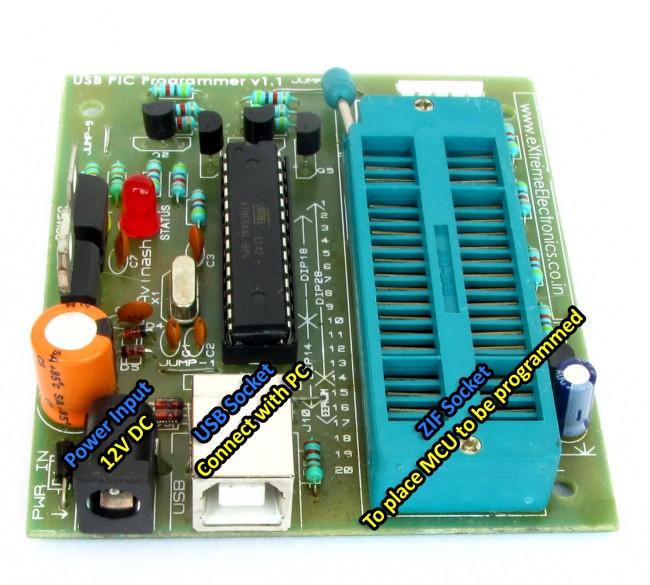 |
Fig. eXtreme Burner Hardware |
The image above shows the actual hardware of eXtreme Burner PIC which is used to program PIC16F and PIC18F series microcontrollers.
Main parts the user interact during normal usage are.
- Power Input Socket - This is used to provide 12V DC supply using the adapter provided in the KIT.
- USB Socket - This provides a connection between your PC and the programmer using the USB Cable.
- ZIF Socket - Zero Insertion Force Socket is where you place the MCU to be programmed. The ZIF socket can accept MCUs with up to 40 PINs. MCUs that have less than 40 PINs should be placed carefully. Their position is shown in the software.
- Indicator LEDs -
- Power LED - Indicates that board is receiving power from DC adapter.
- Status LED - If the programmer is reading or writing data from the MCU this LED will light up.
- ICSP Port - It is a six pin male header which can be used to connect the programmer with your development board to download programs right their without removing the MCU from the development board.
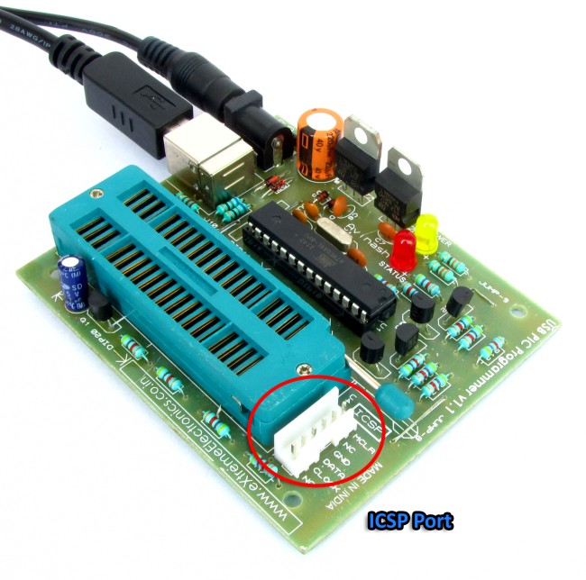 |
Fig. ICSP Port |
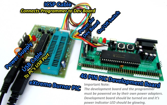 |
Fig. ICSP Based Downloading of Program to Board |
Launching eXtreme Burner - PIC
Launch eXtreme Burner PIC16 from its desktop icon or from the start menu. You will see a screen similar to this :-
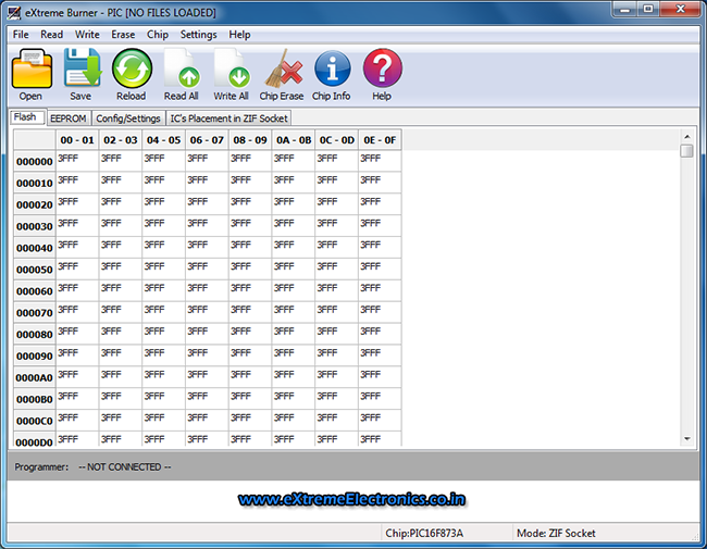 |
Fig. eXtreme Burner - PIC16 |
Let us get familiar with the main window.
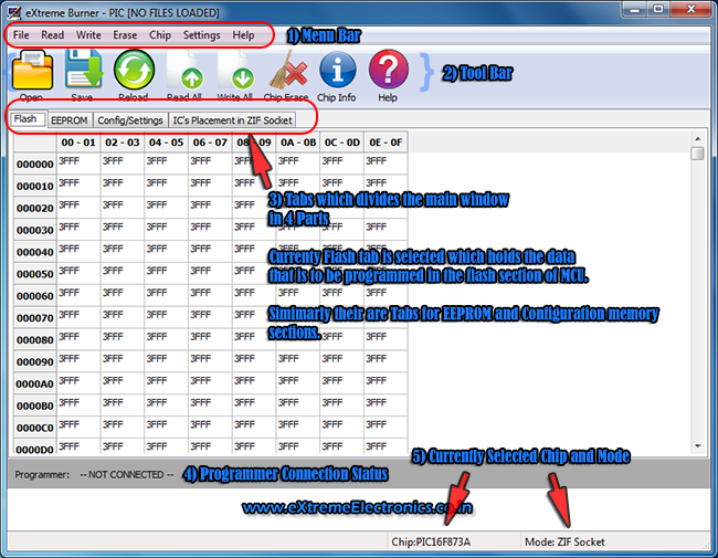 |
Fig. eXtreme Burner - PIC16 Parts of Main Window |
- Menu Bar - It contains commands grouped in Submenus
- File Menu contains command to load and save chip's data.
- Read Menu contains commands to read the three memory sections of pic MCU.
- Write Menu contains commands to write the three memory sections of pic MCU.
- Erase Menu contains commands to erase the three memory sections of pic MCU.
- Chip menu contains a list of supported MCU, you should select the chip that you want to program using this menu before doing any thing.
- Settings menu contains settings for the software. It has Programming mode selection which lets to to a ZIF socket based programming or an ISCP based programming.
- Help menu contains links to help files.
- Tool Bar - It contains some selected commands from the menu bar for quicker access.
- Main Window - It is divided into four different parts.
- Flash - This shows the data buffer for flash memory. When you load a hex file all the data that are targeted for flash section of the memory can be viewed here.
- EEPROM - This shows data buffer for EEPROM memory. When you load a hex file all the data that are targeted for EEPROM section of the memory can be viewed here.
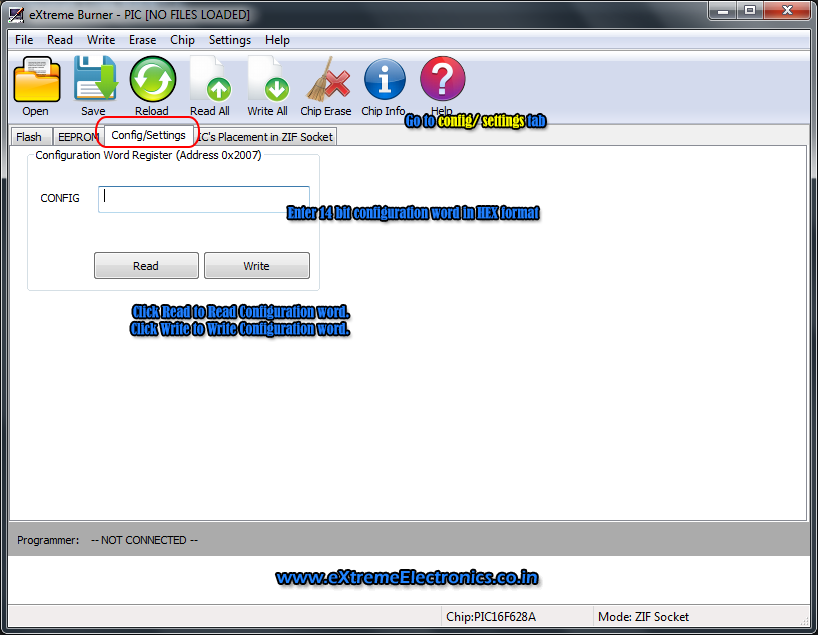
- Configuration memory - This section lets you enter, read and write the configuration word.
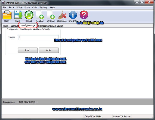 Fig. Configuration Register Tab
 - IC's Placement in ZIF Socket - This parts shows you how specific IC is placed in the ZIF socket. How to correctly position the IC in the ZIF socket.
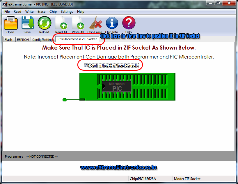 |
Fig. IC's placement in ZIF socket |
Burning a HEX File to PIC MCU
NOTE:
- Read the installation guide to properly install the device on your system.
- Get familiar with eXtreme Burner - PIC Hardware
- Get familiar with eXtreme Burner - PIC Software
Make sure
- eXtreme Burner - PIC is connected to system using USB cable and power is supplied to it using 12V adapter.
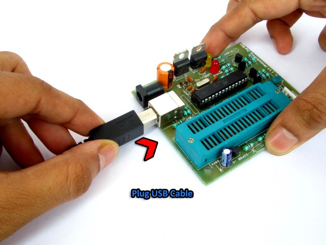 |
Fig. Connect eXtreme Burner - PIC with your PC using USB Cable |
Power up eXtreme Burner PIC with the help of 12V 1A supply provided with the kit. The yellow LED (this may be green in some models) should glow indicating that device is properly powered up.
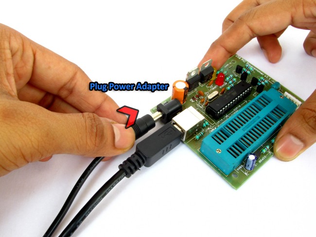 |
Fig. Power up eXtreme Burner - PIC |
Step I
Launch eXtreme Burner PIC16 from its desktop icon or from the start menu. You will see a screen similar to this :-
For more information about this software please refer this.
|
Fig. eXtreme Burner - PIC16 |
Step II
From the Chip menu select the chip you wish to program. For example if you wish to program PIC16F877A select PIC16F877A from the chip menu.
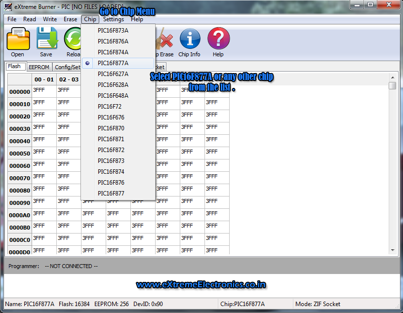 |
Fig. Select chip from chip menu |
Step III
From the Settings menu select the programming mode required.
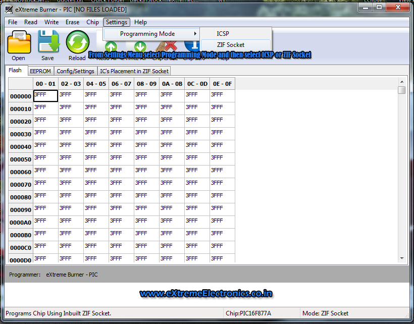 |
Fig. Programming Mode |
Step IV
Loading the HEX file.
From Toolbar select Open Command.
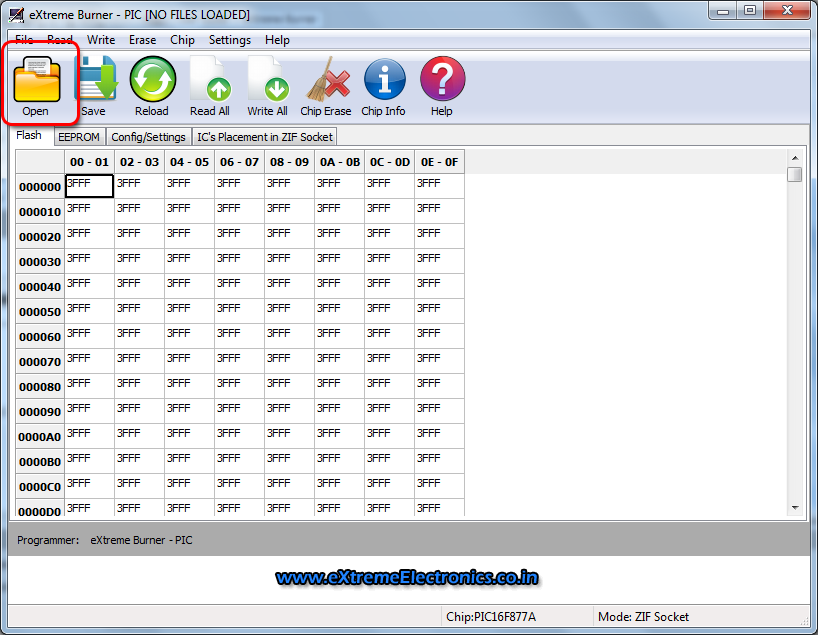 |
Fig. Open |
It will show you the standard file open dialog which will help you choose a hex file from any location on your computer.
Select a hex file and click open.
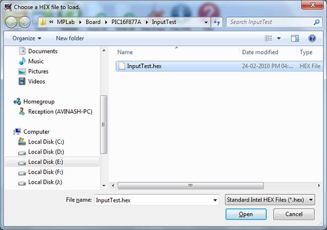 |
Fig. Open |
As stated above that PIC MCUs have three memory section inside the chip. So hex file contains data for these sections. So as soon as you load the hex file, you are presented with the Hex file content report dialog box. This dialog box shows what data were present inside the hex file.
To properly execute the code your hex file must have at least the Flash data and the Configuration data.
EEPROM data is optional and may not be present on all hex file.
Please read this part to know what are the three memory regions inside the pic MCU
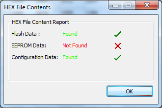 |
Fig. Hex File Report |
Step V
Placing the IC in ZIF socket.
Go to the tab IC's Placement in ZIF socket to view how you should place the particular IC in the ZIF socket.
|
Fig. IC's placement in ZIF socket |
Place the IC in real ZIF socket exactly as show in the image.
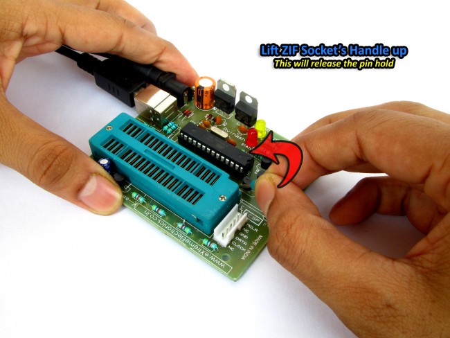 |
Fig. Lift the ZIF socket's handle |
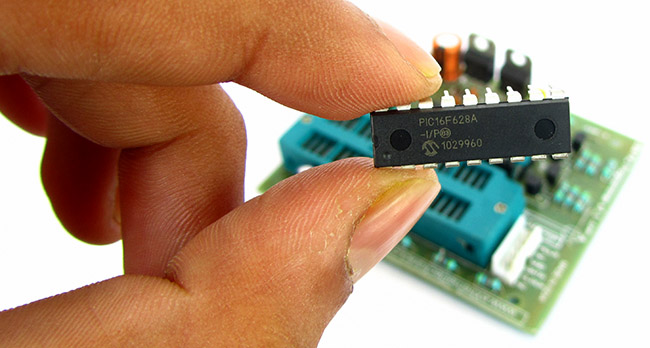 |
Fig. PIC16F628A |
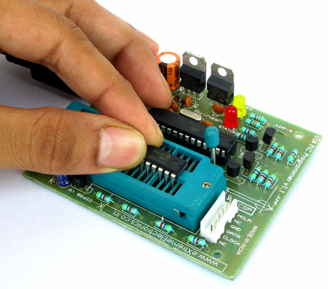 |
Fig. Put it in ZIF Socket |
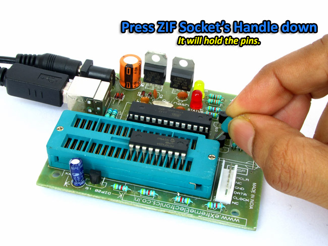 |
Fig. Lock the ZIF socket by pressing the handle downwards |
Step VI
Writing to chip
Click "Write All" from the toolbar.
 |
Fig. From the toolbar select "Write All" |
A progress window will be shown, it shows each action as it is performed by the programmer.
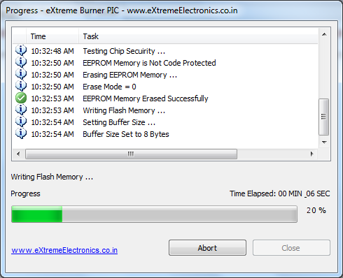 |
Fig. Progress |
Important steps taken by the programmer are :-
- Detecting the programmer hardware.
- Erasing the chip.
- Writing the contents of flash memory.
- Verification of flash memory, this ensures the chip is correctly written. The memory cells are read one by one and matched against their value in the buffer. If each and every cell is matched a verification success message is shown.
- Writing the contents of EEPROM memory.
- Verification of EEPROM memory, this ensures the chip is correctly written. The memory cells are read one by one and matched against their value in the buffer. If each and every cell is matched a verification success message is shown.
- Writing and verification of configuration memory.
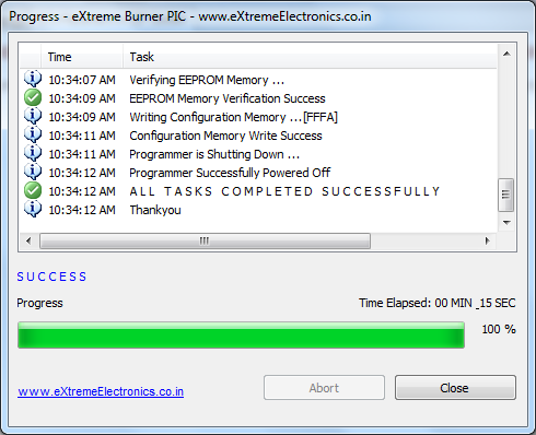 |
Fig. Task Complete |
If each task is completed successfully you will receive a success message at the end.
Back |
Support |
Store |
Facebook |