Motor Control
AVR ATmega8 Bases Line Follower.
Easy to make PID LFR Robot.
DC Motor is the most commonly used actuator in robotics applications. An actuator is a device used to produce motion. DC motors are used to drive wheels in order make the robot move. They are also used to power grippers, arms and weapons( fighting robos). Normally a DC Motor with in built gear box is preferred. One such motor is shown below.
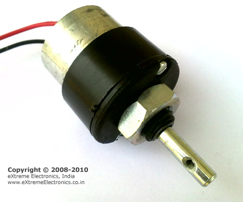 |
A Geared DC Motor. |
They normally consume 400ma to 1000ma current and works off 12v DC Supply. The shaft is compatible with commonly available hobby robotics wheels. They are available in many different RPM(Revolution Per Minutes). Example: 60 RPM, 100 RPM and 200 RPM.
In this tutorial we will learn the basics about these motors and how to control them using a microcontroller.
NOTE:
Many hobby robotics items are available at best rates from eXtreme Electronics Webshop. We deliver them any where in India at low shipping rates.
Control
DC Motor Rotates in one direction when you apply power to its terminals. When you reverse the polarity of the supply it will rotate in other direction.
As a DC Motor require current in the range of 400ma to 1000ma we cannot supply them directly from the MCUs I/O PINs. We need some kind of driver circuit that can deliver more current to the motors. Also a MCU general works of 5v supply but normal motors require a 12v (or 24v) supply. This circuit which is used to control a Motor from MCUs I/O line is called H-BRIDGE circuit. Many easy to use H-Bridge ICs are available like L293. One L293 IC has two H-BRIDGE circuits. So it can control 2 DC Motors.
Our LFR Board has one L293 IC that can control up to two DC Motors with up to 600ma current rating each.
It is a 16 PIN chip. The pin configuration is as follows.|
|
L293D Dual DC Motor Controller. |
|
|
Fig: Motor Controller Using L293d chip. |
The behavior of motor for various input conditions are as follows
A |
B |
|
| Stop | Low |
Low |
| Anticlockwise | Low |
High |
| Clockwise | High |
Low |
| Stop | High |
High |
So you saw you just need to set appropriate levels at two PINs of the microcontroller to control the motor. Since this chip controls two DC motors there are two more output pins (output3 and output4) and two more input pins(input3 and input4). The INPUT3 and INPUT4 controls second motor in the same way as listed above for input A and B. There are also two ENABLE pins they must be high(+5v) for operation, if they are pulled low(GND) motors will stop.
L293D Connection with MCU
Four i/o ports are connected to the four inputs of L293D IC as follows. Two addition lines ENABLE1 and ENABLE2 are used for PWM speed control of DC motors, they are discussed latter. Till then we will keep ENABLE1 and ENABLE2 at logical high states to run the motors at maximum speed.
MCU i/o pin |
Motor |
|
| INPUT1 | PD0 |
MOTOR-B(L) |
| INPUT2 | PD1 |
|
| INPUT3 | PD2 |
MOTOR-A(R) |
| INPUT4 | PD3 |
|
| ENABLE1 | PB1 |
MOTOR-B |
| ENABLE2 | PB2 |
MOTOR-A |
*L=LEFT Motor. R=RIGHT Motor.
Sample Program
This sample program given below starts motor-b in anti-clockwise direction and after a short period of time reverse the direction of rotation. This cycle is repeated as long as the system is powered.
/*
 * BasicMotorDemo.c
 *
 * Created: 20-06-2012 PM 06:20:40
 *  Author: Avinash
 */


#include <avr/io.h>
#include <util/delay.h>

void Wait();

int main(void)
{
   //Make GPIO pins connected to L293D as output.
   DDRD|=((1<<PD3)|(1<<PD2)|(1<<PD1)|(1<<PD0));

   //Also make gpio connected to ENABLE1 and ENABLE2 as output.
   DDRB|=((1<<PB2)|(1<<PB1));

   //Make ENABLE lines high (no speed control, motor runs at max speed)
   PORTB|=((1<<PB2)|(1<<PB1));

   while (1)
   {
         //Run Motor b in counter clockwise direction
         PORTD&=~(1<<PD0); //Clear BIT PD0
         PORTD|=(1<<PD1);  //Set BIT PD1

         Wait();

         //Run Motor b in clockwise direction
         PORTD|=(1<<PD0);  //Set BIT PD0
         PORTD&=~(1<<PD1); //Clear BIT PD1

         Wait();

   }

}

void Wait()
{
   char i;
   for (i=0;i<100;i++)
   _delay_loop_2(0);
}
HEX File Ready to Burn
The hex file ready to burn can be found in the Precompiled HEX Files folder in the Support DVD.
- BasicMotorDemo.hex
Note
If you do not under stand how bits are set or cleared in registers like DDRx or PORTx, see the following tutorial.
Return to Help Index.