Many electrical signals around us are Analog in nature. That means a quantity varies directly with some other quantity. The first quantity is mostly voltage while that second quantity can be anything like temperature, pressure, light, force or acceleration. For example in LM35 temperature sensor the output voltage varies according to the temperature, so if we could measure voltage, we can measure temperature.
But most of our computer (or Microcontrollers) are digital in nature. They can only differentiate between HIGH or LOW level on input pins. For example if input is more than 2.5v it will be read as 1 and if it is below 2.5 then it will be read as 0 (in case of 5v systems). So we cannot measure voltage directly from MCUs. To solve this problem most modern MCUs have an ADC unit. ADC stands for analog to digital converter. It will convert a voltage to a number so that it can be processed by a digital systems like MCU.
This enables us to easily interface all sort of analog devices with MCUs. Some really helpful example of analog devices are
- Light Sensors.
- Temperature Sensors.
- Accelerometers.
- Touch Screens.
- Microphone for Audio Recording.
And possibly many more.
In this tutorials we will learn to use the internal ADC of PIC18 devices (Example is for PIC18F4520 which is a 40 PIN device).
Specifications of ADCs
Most important specification of ADCs is the resolution. This specifies how accurately the ADC measures the analog input signals. Common ADCs are 8 bit, 10 bit and 12 bit. For example if the reference voltage(explained latter) of ADC is 0 to 5v then a 8 bit ADC will break it in 256 divisions so it can measure it accurately up to 5/256 v= 19mV approx. While the 10 bit ADC will break the range in 5/1024 = 4.8mV approx. So you can see that the 8 bit ADC can’t tell the difference between 1mV and 18mV. The ADC in PIC18 are 10 bit.
Other specification include (but not limited to) the sampling rate, that means how fast the ADC can take readings. Microchip claims that pic18f4520’s ADC can go as high as 100K samples per second.
ADC Terminology
Reference Voltage: The reference voltage specifies the minimum and maximum voltage range of analog input. In PIC 18 there are two reference voltage, one is the Vref- and one is Vref+. The Vref- specifies the minimum input voltage of analog input while the Vref+ specifies the maximum. For example if the input signal Vref- is applied to analog input channel then the result of conversion will be 0 and if voltage equal to Vref+ is applied to the input channel the result will be 1023 (max value for 10bit ADC).
 |
Fig.: ADC Reference Voltage. |
The Vref+ and Vref- pins are available in PIN5 and PIN4 of the PIC18F4520 chip. So you can connect the reference voltage here. For a simple design the Vref- is GND and Vref+ is Vcc. As this is such a common configuration that the ADC can be set up to use these reference internally. Therefore you do not need to connect these on the external Vref pins, so you can use them for other purpose.
ADC Channels: The ADC module is connected to several channels via a multiplexer. The multiplexer can connect the input of the ADC to any of the available channels. This allows you to connect many analog signals to the MCU (say 3 temperature sensors). In PIC18F4520 there are 13 analog input channels, they are named AN0, AN1 etc. You can have a look at the pin configuration in the pic18f4520’s datasheet to locate their position.
Acquisition Time: When an specific channel is selected the voltage from that input channel is stored in an internal holding capacitor. It takes some time for the capacitor to get fully charged and become equal to the applied voltage. This time is called acquisition time. The PIC18F4520’s ADC provides a programmable acquisition time, so you can setup the acquisition time. Once acquisition time is over the input channel is disconnected from the source and the conversion begin. The acquisition times depends on several factor like the source impedance, Vdd of the system and temperature. You can refer to the page 227 and 228 in the datasheet for details on its calculation. A safe value is 2.45uS, so acquisition time must be set to any value more than this.
ADC Clock: ADC Requires a clock source to do its conversion, this is called ADC Clock. The time period of the ADC Clock is called TAD. It is also the time required to generate 1 bit of conversion. The ADC requires 11 TAD to do a 10 bit conversion. It can be derived from the CPU clock (called TOSC) by dividing it by a suitable division factor. There are Seven possible option.
- 2 x TOSC
- 4 x TOSC
- 8 x TOSC
- 16 x TOSC
- 32 x TOSC
- 64 x TOSC
- Internal RC
For Correct A/D Conversion, the A/D conversion clock (TAD) must be as short as possible but greater than the minimum TAD . See table 26-25 in PIC18F4520 datasheet (or table 28-29 in PIC18F4550/PIC18F2550 datasheet). It is 0.7uS for PIC18FXXXX device and 1.4uS for PIC18LFXXXX device.
We are running at 20MHz in our PIC Development board so we set prescaler of 32 TOSC.
Our FOSC = 20MHz
Therefore our FOSC = 1/20MHz
                   = 50nS

32 TOSC = 32 x 50 nS
        = 1600nS
        = 1.6uS

1.6 uS is more than the minimum requirement.
You can calculate the value for division factor using the above example in case you are using crystal of other frequency. Also now we have the TAD we can calculate the division factor for acquisition time. Acquisition time can be specified in terms of TAD. It can be set to one of the following values.
- 20 x TAD
- 16 x TAD
- 12 x TAD
- 8 x TAD
- 6 x TAD
- 4 x TAD
- 2 x TAD
- 0 x TAD
As we saw in above paragraph that the safe acquisition time is 2.45uS, so we select 2 x TAD as acquisition time.
TACQ=2 x TAD
    =2 x 1.6uS (Replacing TAD= 1.6uS)
    =3.2uS
3.2uS is more than required 2.45uS so its ok.
Programming ADC in HI-TECH C for MPLAB
ADC is connect to the PIC CPU by 3 control register and 2 data register. The control registers are used to setup and give commands to the ADC. They also provides the status of ADC. The two data registers holds the 10 bit of converted data. Since each resister in PIC18 is of 8 bits therefore 2 registers are required to hold the 10bit data.
We will develop two functions to support ADC in our projects. One will help initialize the module and other will help us select any of the 13 channels and start the conversion. After the conversion is done it will return us the results.
I am not giving here the description of the control and data registers as they are very clearly explained in PIC18F4520’s datasheet on page 223 to 225. I request you to download the datasheet and read the description so that you will have an Idea of what every bit in the registers do. As I told before, ADC is connected to the CPU via three control register and two data registers. The three control registers are :-
- ADCON0 – Used to select analog input channel,start the conversion, check if the conversion is done and to switch on/off the module.(We use this in ADCRead() function.)
- ADCON1 – Used to Select Voltage reference, and to configure ports as Analog of digital. (We leave these to defaults)
- ADCON2 – Used to select ADC data format, Set acquisition time, ADC clock setup (We setup these in ADCInit() function)
First we configure the ADC to our needs in the ADCInit() function.
//Function to Initialise the ADC Module
void ADCInit()
{
   //We use default value for +/- Vref

   //VCFG0=0,VCFG1=0
   //That means +Vref = Vdd (5v) and -Vref=GEN

   //Port Configuration
   //We also use default value here too
   //All ANx channels are Analog

   /*
      ADCON2

      *ADC Result Right Justified.
      *Acquisition Time = 2TAD
      *Conversion Clock = 32 Tosc
   */

   ADCON2=0b10001010;
}
You can see that we only set up the ADCON2 register.We setup the ADC as follows
- ADC Result format as Right Justified(Explained latter).
- Acquisition time = 2TAD(As Calculated Above)
- Conversion Clock as 32 TOSC(As Calculated Above)
We also leave ADCON1 to defaults, which implies the following
- +VREF is 5v (Our Vcc)
- -VREF is GND
- All ANx channels are Analog. If you need some of them to do digital I/O then setup them accordingly.
Now we have our ADC Module setup, when ever you want to do the ADC Conversion in any channel, simply call ADCRead(). For example to do ADC Conversion on channel 0 and store the result in variable val call the function in the following way.
val=ADCRead(0);
That’s it ! the analog value present on AN0 will be converted to a digital value and stored in variable val.
How the ADCRead() function works?
//Function to Read given ADC channel (0-13)
unsigned int ADCRead(unsigned char ch)
{
   if(ch>13) return 0;  //Invalid Channel

   ADCON0=0x00;

   ADCON0=(ch<<2);   //Select ADC Channel

   ADON=1;  //switch on the adc module

   GODONE=1;  //Start conversion

   while(GODONE); //wait for the conversion to finish

   ADON=0;  //switch off adc

   return ADRES;
}
The first line checks if the input channel provided by the user is valid or not. Then we select ADC channel. After that we switch on the module by setting ADON bit. Then conversion is started by setting the GODONE bit. As soon as the GODONE bit is set to 1 the module starts the conversion process. As long as the module is busy the GODONE bit is HIGH, and when the conversion is complete it is cleared by the module. So we wait in the while loop as long as GODONE is high. Remember that the while loop is empty (a semi colon just after it), so as long as GODONE is high the CPU will do nothing. As soon as GODONE is cleared the while loop breaks and we switch of the module by writing 0 to the ADON bit. Finally the result of conversion is returned, ADRES register holds the converted value.
Demo program to test PIC ADC Code
We will write a very simple program that will demonstrate ADC usage. The program will read ADC channel 0 (AN0 PIN) and display its value on LCD Screen. Before attempting the experiment please read the following tutorials. As you will need the LCD Support in addition to the ADC Interface code.
The program is intended to be compiled using the HI-TECH C for PIC18 using the MPLAB IDE. So if you are not familiar with the build steps please see the following tutorials.
/********************************************************************

ANALOG TO DIGITAL CONVERTOR INTERFACING TEST PROGRAM

---------------------------------------------------------
Simple Program to connect with the internal ADC of PIC MCUs.
The program reads and display the analog input value at AN0.
Requires the PIC18 lcd library.

MCU: PIC18FXXXX Series from Microchip.
Compiler: HI-TECH C Compiler for PIC18 MCUs (http://www.htsoft.com/)

Copyrights 2008-2010 Avinash Gupta
eXtreme Electronics, India

For More Info visit
http://www.eXtremeElectronics.co.in

Mail: me@avinashgupta.com

********************************************************************/
#include <htc.h>

#include "lcd.h"

//Chip Settings
__CONFIG(1,0x0200);
__CONFIG(2,0X1E1F);
__CONFIG(3,0X8100);
__CONFIG(4,0X00C1);
__CONFIG(5,0XC00F);


//Simple Delay Routine
void Wait(unsigned int delay)
{
   for(;delay;delay--)
      __delay_us(100);
}

//Function to Initialise the ADC Module
void ADCInit()
{
   //We use default value for +/- Vref

   //VCFG0=0,VCFG1=0
   //That means +Vref = Vdd (5v) and -Vref=GEN

   //Port Configuration
   //We also use default value here too
   //All ANx channels are Analog

   /*
      ADCON2

      *ADC Result Right Justified.
      *Acquisition Time = 2TAD
      *Conversion Clock = 32 Tosc
   */

   ADCON2=0b10001010;
}

//Function to Read given ADC channel (0-13)
unsigned int ADCRead(unsigned char ch)
{
   if(ch>13) return 0;  //Invalid Channel

   ADCON0=0x00;

   ADCON0=(ch<<2);   //Select ADC Channel

   ADON=1;  //switch on the adc module

   GODONE=1;//Start conversion

   while(GODONE); //wait for the conversion to finish

   ADON=0;  //switch off adc

   return ADRES;
}
void main()
{
   //Let the LCD Module start up
   Wait(100);

   //Initialize the LCD Module
   LCDInit(LS_BLINK);

   //Initialize the ADC Module

   ADCInit();

   //Clear the Module
   LCDClear();

   //Write a string at current cursor pos
   LCDWriteString("ADC Test");

   while(1)
   {
      unsigned int val; //ADC Value

      val=ADCRead(0);   //Read Channel 0
      LCDWriteIntXY(0,1,val,4);

      Wait(1000);
   }


}
Basic PIC Hardware to test the ADC Code.
The following image shows the basic hardware required to run the above code. Note that the crystal frequency is 20MHz, so please use this value only, if you want quick and error free operation. Or if you are experienced enough you can sort out errors if any.
 |
Fig.: Schematic for PIC ADC Test. (Click To Enlarge/Print) |
If you are using our 40 PIN PIC Development Board then most of the hardware is already done for you. You just need to make and attach the LCD Expansion Board to the main Dev Board. RV2, which is a 10K variable resistor is used to feed variable voltage between 0 and 5v to the analog input PIN. When the demo is running you can adjust RV2 can note the change is ADC read out on the LCD Module.
Videos and Pictures
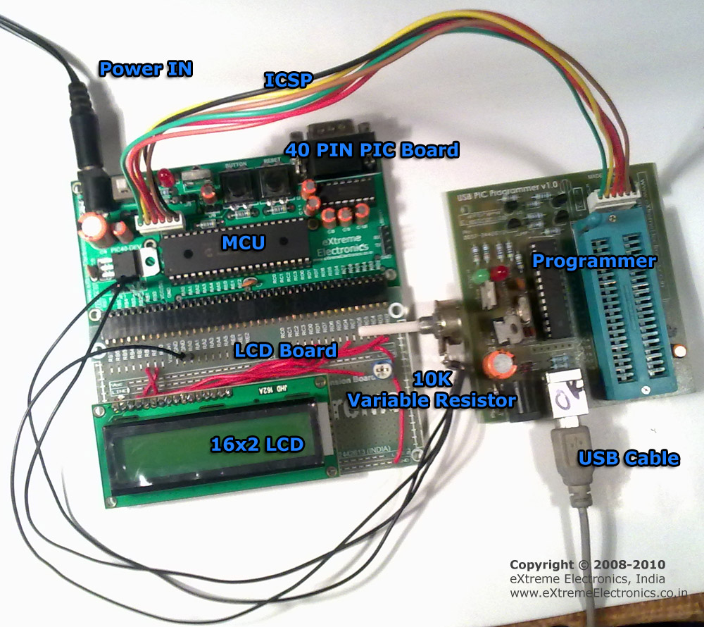 |
Fig.: PIC ADC Demo Hardware Setup. (Click To Enlarge/Print) |
Check your understanding! Take a 1 minute test.
Buy complete kit including PCB, Parts, Programmed MCU, Transformer and Matching IR Remote Control Unit.
Downloads
- Complete MPLAB project for ADC Demo.
- HEX File for PIC ADC Demo.
- Proteus
ISIS Simulation project. Run and debug the code without any hardware setup
directly on your PC.
By
Avinash GuptaJuly 21, 2010
hiiiiiiiiii
it’s really very good site. & very helful for stuents. thaks once again
Pingback: Introduction to PIC Interrupts and their Handling in C | eXtreme Electronics
hi
This is really good article. now iam working in pic24.
i have connected a pressure sensor which gives differential output , to the adc. I used AN0 for +ve input and AN1 for
-ve input and configured the registers. but there is some offset while i read it using the controller. ( subtracting the offset doesnt help). Is there any article like this which helps to read a differential input to the pic24 controller.
Thanks
mit
Thanks a lot for the program admin
If im using mplab code to run the program,what is the asm file would be?
I really interested to know about the line by line execution for a\d program using mplab since i am new to microcontroller
regards
agu
AWESOME WEBSITE.GR8 FOR STUDDENTS
Great tutorial! There’s another one on specifically configuring the PIC18F4550 here: http://www.robotenthusiasts.com/tutorials/?p=14
I noticed something wrong when the ADC Result is Right Justified.
input ADC @1.25V then the output will be zero.. that’s the problem..
after I change my code to left justfied and use the value of ADRESH then it’s all working… why?
if i just use the value of ADRESH and discard the other 2bits of ADRESL then is it the same with I am using only 8bit resolution ADC?
when i copied the code and paste it on new editor then after build it shows error. can you please tell me how can i change the code.
thanks it’s great 🙂
hello every one.
i need to configure timer as well as usart interrupt same time.
note:
am using pic 16f877a controller
compiler: ccs compiler
Hey can anyone send me the MUX-ADC program for pic16f877
Pingback: How to initialize ADC for PIC18f4620?
Pingback: Increasing the sampling rate of ADC in PIC18F4550
hiiii
Good Tutorial .
thanks a lot its really helps
do any one help me on write and read codes in c for EEPROM in PIC18F4520……..??????
@Priti
Thanks
Can i know how do i convert the raw value back to the voltage value and display the decimal value on the LCD. Thanks.
Wow! That’s totally awesome! Thank you very much, your explanation was very clear. I’m writing from Mexico an I can tell you ¡Viva India Cabrones!
hai avinash, very good and elaborate tutorial, surely helpful for many. thanks a lot, but i am sorry to say this, there needs a little correction in this line. i am sure it has happened by mistake
Our FOSC = 20MHz
Therefore our FOSC = 1/20MHz // sorry it is not FOSC
= 50nS its Tosc right
32 TOSC = 32 x 50 nS
= 1600nS
= 1.6uS
1.6 uS is more than the minimum requirement.
I am working on a project right know where I have created a simple transmitter and receiver circuit. The transmitter sends out a carrier wave at 24MHz with no intelligence on it. I am trying to make it so that when I get closer to the transmitter with my handheld receiver it will light a series of 5 LED’s based on the signal strength. Right now I am trying to use the PIC18F452 to do this using the built in ADC. The more I read about ADC the more confused I become as to how I might achieve this because originally I was going to do tests to figure out what my maximum received voltage is from my transmitter to my receiver and set that as the max and use 0V as the minimum however, it seems to be that you need to have your maximum and minimum voltages plugged into pins 4 and 5 on the PIC and since I am using radio waves which cannot be plugged in I am confused as to how this might be done. So my question is do you think this is possible with the PIC18F452 and how might someone more experienced than me go about doing this?
Thanks!
hi m doing my project on conversion of conventional cockpit in glass cockpit. therefore wanna know about how micro controller can be used to give multiple digital output to multifunctional displays through bus.
if u know please help otherwise don’t paste this shit tutorials go n teach primary class ok..
Exceptionally well presented article, helped me understand the significance of Acquisition Time and Clock values during ADC conversion (as opposed to just the dry facts of the datasheet). Thanks!
hi , great work , the only problem is the MPLAB code doesn’t work ( maybe because I have a different version ) . can I have the same code for mikro c , it would be great , thanks any way .
sir i need info about microcontroller.i want to display 4microsecond time delay between two pulses through microcontroller.
Hi!
I need to activate ADC on PIC16F1508 in order to use a Joystick. I should able to get two outputs. Both should able to calculate the volt and trigger the system. Fo example if the signal >3V and Signal<2V. How can I do that? Right now I have done as below;
while(1)
{
roForward();
__delay_ms(100);
roRight();
__delay_ms(20);
roLeft();
__delay_ms(20);
roBackward();
__delay_ms(100);
}
As you can see the I have used the timer to control the robot. Instead of Timer I want the joystick to step in. I am using MPLABPX.
Thanks.
hi….
its very great.. now i am very much cleared in ADC concept.. actually im facing trouble while the interviewer asking about ADC.. now i m clear..
thanks a lot
hi.. this site is very good.. really good tutorial.. thnx for this.
i am working on pic 16f886 and 16f877. can u change this adc code for this micro controller.? pls give me some suggestion, help.
i need this pls….
hi,i am making a project to measure room temperature using lm35 and pic 18f4520.i am displaying the temperature using two seven segment displays.however the display comes out as 00.what is going wrong?
Pingback: how to use analog sensor+ADC+pic16F877A
its very good article, thank you posting this type of article
Good tutorials,added to my tool kit!
Very Good tutorial ,
please can I know is it important to put any capacitor or resistors to connect Vref+ to the voltage value that I need
it is a good tutorial.i want one clarification.To which pin number analog input is applied to ADC of pic16f4520.
sir i want one clarification.To which pin no analog input is applied to ADC of pic16f4520
#include
error shows
ADCDemo_PIC18F4520_20MHz/xxx/adctest.c:21: error: Can’t open include file “htc.h”
#include
how can i remove this error
you need htc.c header file
replace this comand #include
with this this #include “htc.h”
and copy the htc.c file in the folder where your source file is
Hi
thanks alot for this article but ihave some problem in #include
i’m using pic16f877a
and i have a question i need to convert dc volt to digital using pic c how can i do that ?
i’m sorry but this program doesn’t work with me
Thank you! This tutorial is very helpful!
Hi,
A good description for pic18. I am a new comer in this filed,can you please help me out in understanding ADC working and programming for pic16f676. I will be very much thankful for the same.
Thanks in advance.
can you please discuss how can we use external adc chip with pic microcontroller for better resolution and high speed conversation as you discussed for the AVR microcontroller. THANKS.
hello. how to configure the water sensor sn-ws-11304p to analog signal in pic18f4580.???
hello. how to configure the to analog signal in pic18f4580.???
Very good tutorial,
Congratulations!
i have one doubt:
If in PIC18FXXXX device minimum TAD is 0.7uS, why do you consider 32 x Tosc and not 16 x Tosc ?
This was my orientation:
”
Our FOSC = 20MHz
Therefore our Tosc = 1/20MHz
= 50nS
16 Tosc = 16 x 50 nS
= 800nS
= 0.8uS
0.8 uS is more than the minimum requirement.
”
Best Regards,
Fernando.
Pingback: [PIC] problem in lcd4bit...hardware
how to convert this program to HEX file?
@sagar, ok will tell you that. But please tell us from how long you are reading our site?
Hello to everyone, I am using PIC16F877A and whenever i am trying to set the GO/DONE bit it shows me an error as” undefined identifier “GODONE”., I tried to write in all the possible way but unsuccessful.
I am using MPLAB IDE with Hi-TECH as compiler.Is any one there having the solution….?
any kind of support will be appreciated.
Thanks
ADCON0=(ch<<2); //Select ADC Channel
in this line, for what the number "2" mentioned?
can we use only two input channels of the ADC?
may i replace it with "8" ?
please reply.
@Suthan,
Do you know C programming language?
If yes, what is the name of this operator?
<<
Hi Avunash
thanks for your tutorial….
Do you have any project on SENT Protocol (digital Output)
Hi Avinash sir!
Your website is really very great and very much informative.All explanation are provided in very easy and lucid manner which makes learning easier.
Actually i am working on light sensor using lm35 on pic 18f4520,I just want to sense the temp between -25 degree Celsius to 25 degree Celsius so what code should I use for the same.
I have a query regarding adc.
For my project i’m using Pic18f4520 with c18 compiler mplab. I want to print adc 10bit converted data onto virtual terminal.the adc converted data needs to be converted into ascii characters for this..how can acheive this?
hi ,
i just called you a few minute ago – if you have time , i have a project on charge controller
@Paul,
Please provide details of the requirement.
can i use two different vref like 2.8 volt 1.7 volt in a prog. that means three state input in a pin like (2.8 to 5 is one input, 1.7 to 2.7 another input and bellow 1.7 is another input.) both are covert to digital values, then i want to compare… is it possible….
@avinash
Hi @avinash i have been a follower of your tutorials and i have learnt alot thanks man!!!
Dear Sir,
I am Shri M and Pursuing B.E final year. I came across your site and it’s really to say that your web site is amazing which provides new trends techno project ideas. So, I am doing project on the title “Temperature control in PROTEUS using ADC with motor attached to it”. Its like when temperature is high then RPM of motor should be more and vise versa. In addition to that I needed to add any feature by adding TRANSISTOR. But I am not getting sir. Please help me out this. I saw your all projects So, your one of the expert.
Please send me the design of such project and its C-code. I am using 8051 or 8951. Please send me ADC-Motor-LCD-TRANSISTOR-Any other feature. Please send sir and your help will be like star for me. Really I needed your help.
Thanking You,
Shri M
shrshr03@rediffmail.com
im using multiple channel adc of pic microcontroller …….all the result going to display is right but there is a cross talk effect menas one chanels changes effects next channels result……..plwasw give me some solution for that,,,,,,,,,,,,