 |
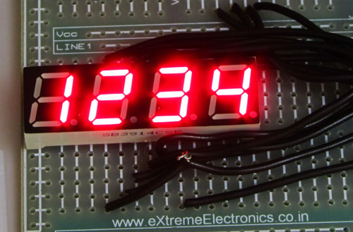
A four digit seven segment display. |
The image above shows a four digit seven segment display. These type of displays are widely used to present numerical data to users. Example includes clocks, panel meters, microwave ovens, refrigerators etc. As you can see in a four digit displays there are a total of 4 x 7 = 28 segments (made of leds) so you may think that they will require lots of i/o pins of MCU. But in reality a small trick can greatly reduce the number of i/o pins required.
The trick is to activate only one digit at a time. All the segments of each four digit are connected in parallel and common of each four digit is tried to MCUs i/o port via transistors. That means MCU can select any digit and put the segment data which drives the segments. Only the selected digit will light up. Then next digit is selected and segment data is changed according to the digit that must be shown in that place. Similarly each digit is selected and shown. This is done fast enough that the human I cannot see the movement. We can see all four digit lit at the same time as shown in the figure above.
 |
Multiplexed Seven Segment wiring |
To display any four digit number, say 1234 on the display. The following steps are taken.
First the display 1 is select by making SEL1 line high (keeping all other SELx line low), now any segment data sent from MCU will be visible only on DISP1. Now we send the segment data for ‘4’, thus it is shown on the DIGIT1.
After some time we select digit 2 by setting SEL2 line high (keeping all other SELx line low) and sending segment data that shows ‘3’ on display. ‘3’ is shown on DIGIT2
After some time we select digit 3 by setting SEL3 line high (keeping all other SELx line low) and sending segment data that shows ‘2’ on display. ‘2’ is shown on DIGIT3
After some time we select digit 4 by setting SEL4 line high (keeping all other SELx line low) and sending segment data that shows ‘1’ on display. ‘1’ is shown on DIGIT2
we repeat the above steps. And we do so fast enough that human eye cannot catch the trick and see all four digits lit at the same time.
Implementing it using PIC MCU
We will use PIC18 series MCU to implement the above technique. To make the refreshing of display automatic we will use TIMER0 module. We set it to interrupt on overflow. If you are new to TIMERs and PIC Interrupt handling please see the following tutorials.
Timer Interrupt Service Routine(ISR) is automatically called by the hardware at specified interval. This ISR switch to next display and changes the segment data according to the digit to be show on that display. If it is on last display it switch back to display number 1. The data that is shown in the display is store in an array named digits[4]. You can modify the digits[] to change the display. For example if you want to display "1234" you need to do the following :-
digit[0]=4;
digit[1]=3;
digit[2]=2;
digit[3]=1;
We have provided a utility function
void SevenSegPrint(uint16_t num)
Which takes a 16 bit integer argument and splits it into individual digits and updates the digits[] array.
To display "1234" using the above function you simply need to call
SevenSegPrint(1234);
or
int number=1234;
SevenSegPrint(number);
Sample Code in HI-TECH C
/******************************************************************************

Title:

   Demo program to show the use of multiplexed seven segment module.

Description:
   Segment (a,b,c,d,e,f,c,dp connected to RD0,1,2,3,4,5,6,7)
   via 330 ohm resistors.

   Selection lines disp1(unit place),disp2,disp3,disp4(thousand place)

   connected to RA0,1,2,3

   The PIC18F4520 MCU Must be clocked by a 20MHz crystal

   For More information visit
   http://www.eXtremeElectronics.co.in
   (then search 'seven segment mux pic')


Author:
   Avinash Gupta.
   avinash@eXtremeElectronics.co.in

Copyright:
   eXtreme Electronics, India 2008- 2011

Notice:
   No part of this work can be copied or published in electronic or
   printed form without proper permission from the Original Creators.

   ONLY INTENDED FOR EDUCATIONAL, HOBBY AND PERSONAL USE.
   COMMERCIAL USE IS STRICTLY PROHIBITED.


Disclaimer of Warranty.

   THERE IS NO WARRANTY FOR THE PROGRAM, TO THE EXTENT PERMITTED BY APPLICABLE LAW.
   EXCEPT WHEN OTHERWISE STATED IN WRITING THE COPYRIGHT HOLDERS AND/OR OTHER
   PARTIES PROVIDE THE PROGRAM “AS IS” WITHOUT WARRANTY OF ANY KIND, EITHER
   EXPRESSED OR IMPLIED, INCLUDING, BUT NOT LIMITED TO, THE IMPLIED WARRANTIES

   OF MERCHANTABILITY AND FITNESS FOR A PARTICULAR PURPOSE.
   THE ENTIRE RISK AS TO THE QUALITY AND PERFORMANCE OF THE PROGRAM IS WITH YOU.
   SHOULD THE PROGRAM PROVE DEFECTIVE, YOU ASSUME THE COST OF ALL NECESSARY
   SERVICING, REPAIR OR CORRECTION.

******************************************************************************/

#include <htc.h>

#include "types.h"

#define _XTAL_FREQ 20000000ul

//Chip Settings
__CONFIG(1,0x0200);
__CONFIG(2,0X1E1F);
__CONFIG(3,0X8100);
__CONFIG(4,0X0081);
__CONFIG(5,0XC00F);


//Configure i/o ports where display is connected
//below is segment data port
#define SEVENSEG_TRIS   TRISD
#define SEVENSEG_PORT   PORTD

//below is disp select data port
#define SEVENSEG_CMN_TRIS  TRISA
#define SEVENSEG_CMN_PORT  PORTA

uint8_t digits[4]={0,0,0,0};


//Simple Delay Routine
void Wait(unsigned int delay)
{
   for(;delay;delay--)
      __delay_us(100);
}

void SevenSegment(uint8_t num)
{
   switch(num)
   {
      case 0:
                  //  .GFEDCBA

         SEVENSEG_PORT= 0B00111111;
         break;

      case 1:
               //      .GFEDCBA
         SEVENSEG_PORT= 0B00000110;
         break;

      case 2:
               //      .GFEDCBA

         SEVENSEG_PORT= 0B01011011;
         break;

      case 3:
               //      .GFEDCBA
         SEVENSEG_PORT= 0B01001111;
         break;

      case 4:
               //      .GFEDCBA

         SEVENSEG_PORT= 0B01100110;
         break;

      case 5:
               //      .GFEDCBA
         SEVENSEG_PORT= 0B01101101;
         break;

      case 6:
               //      .GFEDCBA

         SEVENSEG_PORT= 0B01111101;
         break;
      case 7:
               //      .GFEDCBA
         SEVENSEG_PORT= 0B00000111;
         break;

      case 8:
               //      .GFEDCBA

         SEVENSEG_PORT= 0B01111111;
         break;

      case 9:
               //      .GFEDCBA
         SEVENSEG_PORT= 0B01101111;
         break;
   }
}


void SevenSegInit()
{
   //Setup i/o ports
   SEVENSEG_TRIS=0X00;
   SEVENSEG_CMN_TRIS=0B11110000;

   SEVENSEG_CMN_PORT=0B00000001;

   //Setup Timer0
   T0PS0=1; //Prescaler is divide by 256

   T0PS1=1;
   T0PS2=1;

   PSA=0;      //Timer Clock Source is from Prescaler

   T0CS=0;     //Prescaler gets clock from FCPU (5MHz)

   T08BIT=1;   //8 BIT MODE

   TMR0IE=1;   //Enable TIMER0 Interrupt
   PEIE=1;     //Enable Peripheral Interrupt

   GIE=1;      //Enable INTs globally

   TMR0ON=1;   //Now start the timer!
}

void SevenSegPrint(uint16_t num)
{
   /*


   This function breaks apart a given integer into separete digits
   and writes them to the display array i.e. digits[]

   */
   uint8_t i=0;
   uint8_t j;
   if(num>9999) return;
   while(num)
   {
      digits[i]=num%10;
      i++;

      num=num/10;
   }
   for(j=i;j<4;j++) digits[j]=0;
}


void SevenSegISR()
{
   /*

   This interrupt service routine (ISR)
   Updates the displays

   */

   TMR0=150;

   static uint8_t i;

   if(i==3)
   {
      //If on last display then come
      //back to first.
      i=0;

   }
   else

   {
      //Goto Next display
      i++;
   }


   //Activate a display according to i
   SEVENSEG_CMN_PORT=((SEVENSEG_CMN_PORT & 0xf0)|(1<<i));

   //Write the digit[i] in the ith display.

   SevenSegment(digits[i]);
}

//Main Interrupt Service Routine (ISR)
void interrupt ISR()
{
   //Check if it is TMR0 Overflow ISR
   if(TMR0IE && TMR0IF)
   {
      //Call the SevenSegISR
      SevenSegISR();

      //Clear Flag

      TMR0IF=0;
   }
}

void main()
{
   //Initialize the Seven Segment Subsystem
   SevenSegInit();

   //Print a number to display
   SevenSegPrint(1234);

   //Do nothing, just loop!

   while(1);

}
To compile the above code you will need the MPLab IDE and HI-TECH C for PIC18. Both are available free at Microchips Website.
- Download Microchip’s MPLAB v8.70
- HI-TECH C Compiler for PIC18 MCUs – Lite mode v9.66 (Requires free registration)
If you are new to these tools then please see the following tutorials :-
- PIC Hello Word Project (Please read carefully and setup the software exactly as described)
Burning the HEX File to PIC MCU
Hex file contains data for three different segments,
- The FLASH (Stores the program)
- The EEPROM (This is a non volatile memory that can be accessed(read/write) by the program. It retains the data even when MCU is switch off, you can specify EEPROMs initial content in hex file. In this project this feature is not required so our hex file DO NOT contain the initial EEPROM contents.
- CONFIG bytes are a special location inside the chip that is used to configure many aspects of the chip like clock source, brown out detector, watch timer, startup times. See page 249 on PIC18F4520’s datasheet. This section is most important for proper working of program so make sure this section is programmed when you write the chip. If you use our USB PIC Programmer. Then as soon as you load the hex file it shows the sections that are present on the hex file.
 |
HEX File Report |
As you can see it states that Flash Data (Your Program), and Configuration Data are present on the hex file, while EEPROM data is not present. When you are ready to transfer the data to the chip select "Write All" from the toolbar or Select menu Write->All. This ensures that Configuration memory is also written. If you write only the Flash section(By selecting Write->Flash) the program WON’T WORK.
You need to take similar steps when using other programmers like PICKIT3 etc.
Schematic for Multiplexed Seven Segment Display
 |
Schematic for 7 Seg Mux with PIC18F4520(Click To Enlarge …) |
|
Multiplexed Seven Segment wiring |
Circuit Building Tips
We use our PIC Development Board for making the above demo project. The PIC Development Board has all the core circuitry to sustain the MCU while the project specific part is developed on the expansion board.
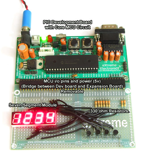 |
Multiplexed Seven Segment Display Setup |
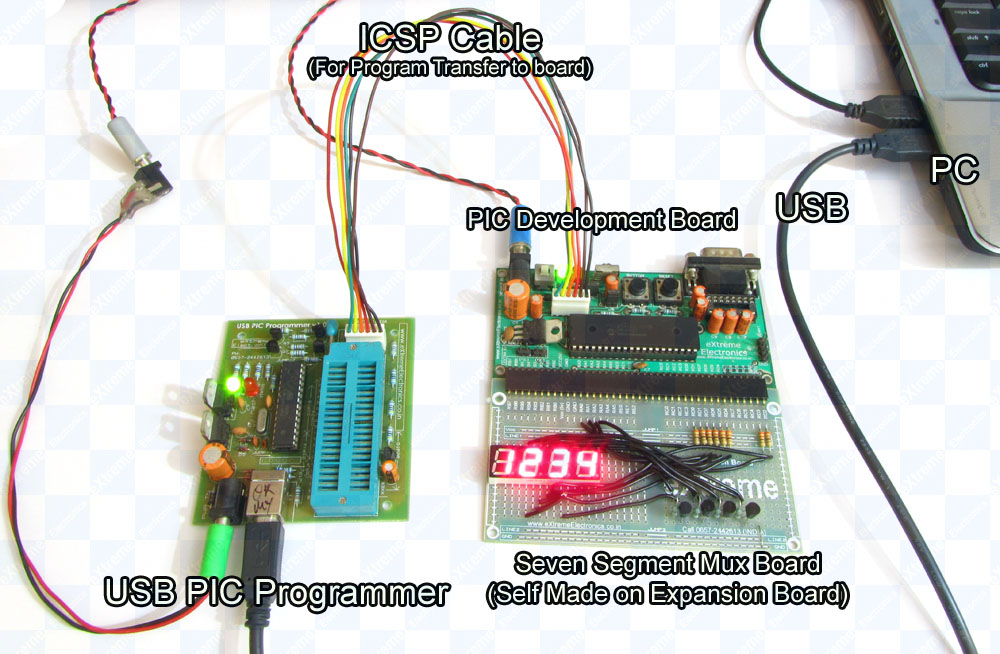 |
Multiplexed Seven Segment Display Setup |
Help Us!
We try to publish beginner friendly tutorials for latest subjects in embedded system as fast as we can. If you like these tutorials and they have helped you solve problems, please help us in return. You can donate any amount as you like securely using a Credit or Debit Card or Paypal.
We would be very thankful for your kind help.
Downloads
- Complete MPLab Project for PIC18F4520 running at 20MHz
- Hex File Ready to burn for PIC18F4520 running at 20MHz
- Complete MPLab Project for PIC18F4550 running at 48MHz
- Hex File Ready to burn for PIC18F4550 running at 48MHz
Subscribe!
Don’t miss any article get them right in your inbox! Subscribe to our feeds powered by Feedburner.
Coming Up Next …
By
Avinash Gupta
www.AvinashGupta.com
me@avinashgupta.com
Bro, there is a mistake in your multiplexing diagram. The emitters of the 4 transistors are tied together, but they are not pulled high or low ie to gnd or vcc.
Also you havent specified if your 7 segment display type. Is it common anode or common cathode??
From the “switch” instruction I infer its Common Cathode. I don’t understand too how the transistors work, if u could give us a low level of the digits from the display
Sorry, I correct myself :it’s “low level DIAGRAM”
Pingback: Efficient way to make a timer circuit
could u pls upload the project for pic18f4550?
Will any changes have to be made in the code, if one is using pic18f4550 in place of pic18f4520?
Hi
I work on 8 Bit ,microchip Hardware ,software ,in order to convert analog,Digital Ic based electronics to Micro Controlled , controlling AC to DC power Supplies.An associationwith you will be appreciated,
Thanks
gupta
good but i need seven segment code for pic 16f690
Thnx…………
Pingback: Looking for a PIC program for battery voltage indicator cum cut off circuit..... - Page 2
Mr. Avinash ,
probably “Complete MPLab Project for PIC18F4520 running at 20MHz” zip folder is damaged, could not be opened.
regards,
Uttam
Hello…
i think there is some thing you forgot to add the emitter terminal of all the transistor(BC548) is sorted and left NC.
i think it must be connected to ground….
Thanks
ismail
@Ismail,
Yes you are right !
Thanks for pointing out !
Will correct it soon.
and one more doubt… do you really think there no need of pullups for BC548 and after pull ups the collector should connect to the Common cathode terminal of 7 segment
Ismail
Here is a program that you can use to get hex, dec or binary value of the port to display a number. This program will save you time. Download link: https://drive.google.com/file/d/0B1WraqbzoZtRVlR1VE56TG04NDg/edit?usp=docslist_api
Hope this program help you guys like it helped me.
No virus..
where can i find the “types.h”
#include
#include “types.h”
#define _XTAL_FREQ 20000000ul
WHERE CAN I FIND THE types.h
please reply
Sur i need yor help to make a display as under
input 4 to 20 ma
display 00 99
i hope i will yor great hrlp to solve my problum
Thank you
I am using Atmel MIC 89s52,I have problem with FND display getting partially illuminated ,which is not required to glow, Please helpme
Anto