Tag Archives: atmega

Simple Single Motor Control using AVR ATmega16

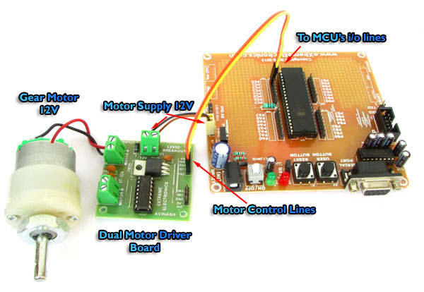
Microcontrollers are good when it comes to brain, but to do anything in real world they need muscles too ! Their muscles are electromechanical actuators like motors. Their are several types of motor available to do various type of motion. The simplest of them are DC motors. They can generate rotary motion and when wheels are attached to their shaft they can be used to move a body. Applications include motion of a robot on flat surface like a floor. Normally a DC motors runs at a high RPM, so to slow it down a gear head is attached in front of it. This makes RPM come down to values such as 50 RPM to 500 RPM. This also increase the torque online casino no deposit generated by the motor. The image below shows a 12v DC Gear Motor. The front black portion contains the gear assembly. Fig. A DC Gear Motor In this tutorial we will learn the basics about these motors and how to control them using a microcontroller. DC Motor Rotates in one direction when you apply power to its terminals. When you reverse the polarity of the supply it will rotate in opposite direction. Since a DC Motor requires current in the range of 400ma to 1000ma we cannot supply them directly from the MCUs I/O […]

Remote Temperature Monitoring using GSM – AVR Project

If you want a live demo of this, please register from the link given below. (Only in Pune) REGISTER NOW! This project can also be implemented using a PIC18F4520 microcontroller. Temperature monitoring have wide application in daily life. In modern day keeping an eye on temperature of places such as server rooms, hospital rooms, warehouses and green houses can help solve many problems. But with the use of normal temperature sensors, someone needs to go to the place in order to view the temperature. But with the development of GSM network, one can easily connect the sensor with GSM network, so that you don’t need to be present near the sensor in order to view the temperature. You can just pick up your cell phone and send a request to your sensor by a text message and in no time you will receive the temperature of the remote place ! The advantage is the you don’t need any kind of "special" device at the receiver end. You can use any cell phone to view the remote temperature. This reduces cost as you already have a cell phone. Other benefit is that the range is not limited. You can be at any place in the world (with mobile coverage of course!), to request temperature data from your room. Fig. SMS Based […]

Sending and Receiving SMS using SIM300 GSM Module

If you want a live demo of this, please register from the link given below. (Only in Pune) REGISTER NOW! This project can also be implemented using a PIC18F4520 microcontroller. We have schematic and C library available. Hi friends in this part we will have a look at the functions related to text messages. By the end of this article you will have a clear idea of how to wait for a text message, read the message, send a new text message and deleted a received message. We have already discussed the basics of SIM300 GSM Module interface with AVR MCU in our previous tutorial you can refer that article to know about the schematic and basic communication code. GSM Module SIM300 Interface with AVR After reading the above article you will know how we have connected the SIM300, AVR ATmega32 and LCD Module to make a basic test rig. Also covered in the article is the detail about the communication method between SIM300 and AVR which is called asynchronous serial communication, done using AVR’s USART peripheral. The article shows you how to use the AVR USART library to send and receive data to/from the GSM Module. We have also discussed the command response method used for the interfacing with the module. Working code is provided that shows you how […]

Time Input Dialog for Graphic LCD

GUI Frameworks of all modern OS like Windows, Linux (Qt & GTK+), MAC etc have a concept of standard dialogs. For example all applications running under Windows shows the same file open dialog for selecting a file. Similarly their are standard dialogs for folder selection, colour selection, font selection etc. This concept has several advantages, and the most important is a easy user interface. Since the user is already familiar with file selection in one application, he/she can use file open dialog of any application. Building on the same concept our GUI framework for ProGFX (avr glcd driver) will too have many standard dialogs for common user interface. In this tutorial we will build the "Time Input Dialog" that helps programmer ask the user to input time. The time could be anything like :- "On" or "Off" time for a relay in a timer application. Alarm time in an alarm clock application. Period start time in a school bell application. And many others. The programmer just need to call the function. void ShowGetTimeDlg(uint8_t *h,uint8_t *m,uint8_t *s,uint8_t *am_pm) It takes four parameters hour, minutes, second and am_pm. All parameters are passed by reference(pointer actually), this is because the function modifies the value of those variables. It shows a dialog as shown below :- Time Input Dialog The user can use the […]

DS1307 I2C RTCC Interface using SoftI2C lib

In the last tutorial, I explained you how to use our SoftI2C library to read and write a 24CXX series I2C EEPROM. Now I will continue our exploration and write a register access layer for the DS1307 chip. The DS1307 chip is a real time clock and calendar IC. The register access layer that we will develop provides the application programmer with function that reads and write the registers of DS1307. Remember that any piece of hardware appears to the CPU as a set of registers only. DS1307 has :- Seven Registers (from 0x00 to 0x06) that are used for timekeeping functions. One CONTROL register(0x07) for square wave generation setting (we don’t use this for simplicity). 56 bytes of battery backup RAM (from 0x08 to 0x3F) Fig. : A Simple DS1307 RTC Module.   Once the application programmer has access to functions that reads and writes to any register (specified by its address) inside DS1307 ic, he/she can easily get and set the time infos like sec,min,hour, am/pm, date,month,year etc. The register access layer is built over the core Soft I2C layer. The register access layer consists of the following three functions. void DS1307Init(void) { SoftI2CInit(); } /*************************************************** Function To Read Internal Registers of DS1307 ——————————————— address : Address of the register data: value of register is copied to this. […]

AVR Graphic LCD and Accelerometer Demo

Hello All!, Accelerometer applications are hot these days. So today I will show you how you can easily make a accelerometer add on for your AVR GLCD Board. Once you make this you can plug it into the AVR GLCD Board any time you wish to run a accelerometer based application on it. I will also provide a simple Open Source App for the AVR GLCD Board that can be used to test the accelerometer in no time. Developers can use this demo as a base for any accelerometer based app. Things you will need are A Veroboard or general purpose prototyping PCB (dotted one, not the line one). Female Burg Strips Female Burg Strip R/A MMA7260 Accelerometer Board Fig.: A Veroboard Marked for Cutting   Fig.: Veroboard Cut to Size   Fig.: Burg Strip Female   Fig.: Burg Strip Female Soldered to Veroboard.   Fig.: Burg Strip Female Soldered to Veroboard.   Fig.: 5 PIN Burg Strip Female Right Angle   Fig.: R/A Burg Strip Soldered.   Fig.: Just Ready!   Fig.: AVR GLD Dev Board   Fig.: Accelerometer Expansion Board Connected   Fig.: Accelerometer Connected.   Fig.: Accelerometer Connected with AVR GLCD Board   Fig.: AVR Accelerometer Ready! Connections     CONNECT TO GND Ground Supply Ground (EXP Port) VDD 3.3 V OUT SLEEP Sel2 G Select Pin2 […]

Remote Controlled Fan Regulator using ATmega8

This device can be used to remotely control the speed of an AC fan and to switch it on or off. The remote control is a cheap NEC Format remote, usually supplied with small DVD players. Three buttons are used to command the circuit. The UP key increase the fan’s speed while the DOWN key decrease it. The ENTER key is used to switch on or off the fan. The unit provides 10 way speed control from 0 to 9. The current speed is displayed in a seven segment display. The yellow LED on the PCB indicates the power status of the load. If the load is switched off using the R/C then the LED will also be switched off. In the Video below you can check out the project in action. The main parts of the circuit is labeled below. The seven segment display used to show the current speed level. The TSOP1738 sensor is used to pick up commands from remote control. The Yellow LED indicates the power status of the load. OUT – Here the AC load is connected in series. Tested on 220v 50Hz AC line. IN – Power supply from a 12-0-12 transformer is applied here. MCU – ATmega8 AVR 8 bit Microcontroller. SWITCH – Manual Switch used to operate the unit without the remote […]

AVR Project – Relay Timer with ATmega8 AVR MCU

Timers are widely used in industrial and domestic application for automating tasks. Microcontrollers can be used to design versatile and accurate timers with ease. Here I present a simple timer that can be used to turn on/off a load after user specified time. The Timer uses a standard 16×2 lcd module for user interface (UI). User can set the time using a 3 button keypad. After that Timer is started. While count down is in progress, the time left is displayed on screen. The program use our LCD driver library more details of which can be found in here. Use avr-gcc + AVR Studio to compile. The prototype was developed using xBoard MINI, a low cost easy to use ATmega8 development board. The program was burned to the MCU’s flash memory using eXtreme Burner – AVR Software and Hardware. A basic knowledge of working with different tools of AVR development is required, so please refer to following articles. Note: Fuse Must be set as follows, HIGH FUSE=C9 LOW FUSE=FF (Very Important) If display is blank please adjust RV1 Part List 01 ATmega8-16 PU U1 02 16×2 LCD Module LCD1 03 16 MHz Crystal X1 04 BC548 Transistor Q1 05 1N4007 Diode D1 06 4.7K Resistor R1,R2 07 10K Variable Resistor VR1 08 22pF Disk Capacitor c1,c2 09 0.1uF Disk Capacitor […]

AVR Project – Digital Stop Watch with ATmega8

Hello Friends, In this tutorial we will make a "Digital Stop Watch" using an AVR ATmega8 Microcontroller. This will help you learn many concepts like Multiplexed Seven Segment Display Interfacing Using AVR Timers Using Interrupts And many others too. The code is written in C language for avr-gcc (WinAVR) . Fig.: Digital Stop Watch Prototype Steps to Build the "Digital Stop Watch" using AVR ATmega8 MCU Make the circuit according to the schematic on general purpose PCB or a BreadBoard. Make a project in AVR Studio and add a new file to the project. Copy/paste the "c" code. Set optimization as "o2" and CPU frequency as 16000000Hz. Save and Build the project. You will get a HEX file. Burn this HEX file to an ATmega8 MCU using a tool such as eXtreme Burner AVR. Set High Fuse = C9(Hex) Low Fuse = FF(Hex). How to do this depends on you programmer software. I have use a xBoard MINI development board for fast and easy prototyping. The Displays+Transistors+Key are on the Veroboard while the Core CPU unit + power supply is in the xBoard MINI. It can be programmed "In System" over USB Port using eXtreme Burner – AVR software toolkit. Fig.: Digital Stop Watch made using xBoard MINI   How to Use the "Digital Stop Watch" When initially powered up […]

Using the USART of AVR Microcontrollers : Reading and Writing Data

Till now we have seen the basics of RS232 communication, the function of level converter and the internal USART of AVR micro. After understanding the USART of AVR we have also written a easy to use function to initialize the USART. That was the first step to use RS232. Now we will see how we can actually send/receive data via rs232. As this tutorial is intended for those who are never used USART we will keep the things simple so as to just concentrate on the "USART" part. Of course after you are comfortable with usart you can make it more usable my using interrupt driven mechanism rather than "polling" the usart. So lets get started! In this section we will make two functions :- USARTReadChar() : To read the data (char) from the USART buffer. USARTWriteChar(): To write a given data (char) to the USART. This two functions will demonstrate the use of USART in the most basic and simplest way. After that you can easily write functions that can write strings to USART. Reading From The USART : USARTReadChar() Function. This function will help you read data from the USART. For example if you use your PC to send data to your micro the data is automatically received by the USART of AVR and put in a buffer […]

Using LCD Module with AVRs

When you start working with LCD modules you will start feeling the real power of MCU and your imaginations will be touching sky you will wonder how many exciting a powerful gadgets you can create and that’s so very easily. LCD Modules can present textual information to user. It’s like a cheap “monitor” that you can hook in all of your gadgets. They come in various types. The most popular one can display 2 lines of 16 characters. These can be easily interfaced to MCU’s, thanks to the API( Functions used to easily access the modules) we provide. LCD interfacing is just fun ! Fig: A 16×2 LCD Module Buy LCD Modules Online In India   PIN Configurations. The lcd modules has 16 PINs for interfacing. The details are given below. LCD Module Pin Configuration 1 VSS (GND Supply) 2 VCC (+5V) 3 VEE (Contrast Adjust) 4 RS 5 R/W 6 E 7 DB0 8 DB1 9 DB2 10 DB3 11 DB4 12 DB5 13 DB6 14 DB7 15 LED + 16 LED –   Connection with ATmega8/ATmega168 etc. The lcd module can be easily connected to the any 28 pin AVR MCU like ATmega8/ATmega168/ATmega328 etc. The diagram below shows the LCD connection with AVR MCUs port pins. Fig: Connection with 28 PIN AVR MCUs Connect the required pins of […]