Tag Archives: interrupt

Introduction to PIC Interrupts and their Handling in C

Interrupts are common features in almost all processor family, be it old 8051, AVR, PIC, ARM or the x86 used in desktops. So their in depth and clear knowledge is required for successful system software engineers. This guide will explain the interrupt system in general and their application using PIC18 architecture. We will also learn about handling of interrupts in HI-TECH C for PIC18. What are Interrupts? Interrupts, as the name suggests interrupts the normal execution and Requests and urgent attention of CPU. Interrupts are situations that the CPU can’t predict when they will happen, they can happen any time, so the CPU does not wait for them. So the CPU keeps on doing its normal job unless and interrupt occurs. For example when the USART (Serial Communication Hardware) will receive data is unknown, it can receive data any time. So the CPU keeps on doing its normal job, which may be for example read temperature using LM35 sensor and display on LCD. The CPU keeps on doing the "normal" job, but as soon as the USART receive data it informs the CPU using an interrupt. The CPU save its current state (so that it can resume), and jumps to the ISR (interrupt service routine) immediately. Where we can process the command or put it in a FIFO queue (to […]

Timers in Compare Mode – Part I

Hi Friends, In last tutorials we discussed about the basics of TIMERs of AVR. In this tutorial we will go a step further and use the timer in compare mode . In our first tutorial on timer we set the clock of the timer using a prescaler and then let the timer run and whenever it overflowed it informed us. This way we computed time. But this has its limitations we cannot compute time very accurately. To make it more accurate we can use the compare mode of the timer. In compare mode we load a register called Output Compare Register with a value of our choice and the timer will compare the current value of timer with that of Output Compare Register continuously and when they match the following things can be configured to happen. A related Output Compare Pin can be made to go high,low or toggle automatically. This mode is ideal for generating square waves of different frequency. It can be used to generate PWM signals used to implement a DAC digital to analog converter which can be used to control the speed of DC motors. Simply generate an interrupt and call our handler. On a compare match we can configure the timer to reset it self to 0. This is called CTC – Clear Timer on […]

Multiplexed Seven Segment Displays – Part II

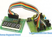
Hi Friends, In last tutorial we discussed about Multiplexing Seven Segment Displays. So you must be very much familiar with the theory. Now let us write the code and design a small project that will make you expert in using these displays in your own projects. We will make a system that can display any number between 0-9999 using four of these displays. We will design a function Print() that we can use on latter projects to easily write integers onto displays. Once we have successfully tested this function we can add to to any project without any problem. This concept of code reuse will make bigger project both easy to make and far less painful. In this sample project we will test our function by using it in a loop to print all numbers from 0-9999. for(i=0;i<10000;i++) { Print(i); Wait(); } Things Required S. No. Item Image 1 28 PIN AVR Dev Board Contains the core AVR circuit including 5v regulator, reset, ISP. 2 Seven Segment Display Module Four common anode displays multiplexed with driver transistors and current limiting resistors. 3 Single Pin Female to Female Burg Wires Used to interconnect the two boards   4 USB AVR Programmer To upload the program to the development board. These are all the things required to get started with seven segment […]

AVR Timers – An Introduction

Timers are standard features of almost every microcontroller. So it is very important to learn their use. Since an AVR microcontroller has very powerful and multifunctional timers, the topic of timer is somewhat “vast”. Moreover there are many different timers on chip. So this section on timers will be multipart. I will be giving basic introduction first. What is a timer ? A timer in simplest term is a register. Timers generally have a resolution of 8 or 16 Bits. So a 8 bit timer is 8Bits wide so capable of holding value withing 0-255. But this register has a magical property ! Its value increases/decreases automatically at a predefined rate (supplied by user). This is the timer clock. And this operation does not need CPU’s intervention. Fig.: Basic Operation Of a Timer. Since Timer works independently of CPU it can be used to measure time accurately. Timer upon certain conditions take some action automatically or inform CPU. One of the basic condition is the situation when timer OVERFLOWS i.e. its counted upto its maximum value (255 for 8 BIT timers) and rolled back to 0. In this situation timer can issue an interrupt and you must write an Interrupt Service Routine (ISR) to handle the event. Fig.: Basic Operation Of a Timer. Using The 8 BIT Timer (TIMER0) The […]