Tag Archives: microcontroller

Development Process of Embedded Systems

Come on, let’s see how an idea in your brain can be transformed to a working embedded systems. What are the key steps you would be following each type you design a system. The key characteristic of embedded system is that it inherits much of its functionality from a well designed program. Everything the embedded system is able to do is through a program which is running inside the microcontroller. This program is a special type of "software" called a firmware. Because it is "firm" in nature because the embedded system once programed and deployed to the end user will be running the same program through out its life time. For example a TV remote control runs the same program which encodes key press data into serial bit stream and sends through an IR transmitter. Same is the case with a MCU inside a pen drive, digital watch and calculators. In contrast a "software" like MS Word or Firefox is not that much "firmly" tied to your PC or Phone. Your PC can run several other software in addition to these and also they can be replaced by their alternatives. So development of embedded software (i.e. firmware) and its installation on microcontroller should be clear to the user. Step I – Development of Program A program is a step by […]

Introduction to AVR Microcontrollers

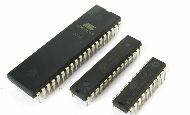
Just what is a microcontroller? To get you understand quickly I define a microcontroller as a single chip computer. Yes it is a full blown computer in its own. It has a C.P.U., RAM, some amount of EEPROM (for secondary storage i.e. permanent storage without power), many on-chip peripherals(Timer,Serial communication, Analogue to Digital converters etc.). If you don’t understand, no problem I will be dealing them in detail in next tutorials. But compared to a P.C. their resources(RAM,speed etc)are less. But that is what is required ! Because P.C. is a general purpose computer, which means it can run thousands of different software that are available for specific needs. Like it can run a game. The same P.C. can run this browser in which you are reading this! It can run a custom solution for banks,railways and airways. It can run a 3D modeling, video editing & image editing software for a production company. Many of these are huge software,requiring lots of memory and CPU power. And a P.C. can run simultaneously many of these ! So to run them the host computer should have enough RAM and CPU power so that it can run heaviest of them. But in case of a microcontroller(aka MCU) which is used for a specific purpose like switching a Microwave oven heating off after […]

AVR RGB LED and Sound Show

Here is a nice and entertaining project created by http://www.ermicro.com . The author has a very good programming, teaching, drawing and artistic skills. The tutorial is well planned and executed. I really liked the RGB LED and Sound show given at the end. I will try it and tell how it works. Till then you can read the rest of the article here. Working with Atmel AVR Microcontroller Basic Pulse Width Modulation (PWM) Peripheral AVR RGB LED and Sound Show. The article also explain various PWM techniques like Fast PWM, Phase correct pwm, phase and frequency correct pwm. You will also learn tone generation using PWM technique. Here is a Video for Various PWM Experiments

AVR Project – ATmega8 Based Multi channel IR Remote

Hi Friends, Today I will present an easy to build Multi channel IR Remote control system. It can control heavy loads (Up to AC 220V 6 Amps or smaller) with a touch of remote control. A total of 5 devices can be controlled from a distance of up to 20 feet. We will be using a standard remote control protocol that is called the NEC format. The NEC format is common in remote controls used with Chinese made CD/DVD players. They are easily available in Indian Markets. They also come in variety of sizes from full to small 21 keys (used in car audio systems). Our system is smart enough, so the user can set which key controls which load. Their are five load indicator LEDs which provide the state of five loads. When the device is powered on for the first time, the load LEDs start to blink one by one. That is the first load LED starts to blink, this means the system is waiting for the user to assign a key for that load. So you should press the key you want to use for that load. Once the system receives the key of your choice it stores it in internal EEPROM. From now on you can use that key to control that specific load. In this […]

AVR Project – ATmega8 Based Smart Code Lock

Here is a project for beginners using Atmel AVR ATmega8. The project uses some techniques that are very useful for designers to learn and utilize. Alphanumeric LCD Module Interfacing. 4×4 Keypad interfacing. PWM Control of LED (Used to dim the back-light of LCD, like in some Nokia Phones) Basic Circuit design for AVR MCUs Connecting relays and other current demanding devices. AVR Studio and project management. compiling using free avr-gcc compiler. Using eXtreme Burner – AVR to burn hex code to AVR MCU. NOTE: Don’t waste time finding each part running from shop to shop. Get all the parts with exact specification in a ready to use kit! Purchase ATmega8 based smart code lock KIT.   Fig.: ATmega8 Based Code Lock Fig.: ATmega8 Based Code Lock Project     Functions of the Project. This device can be used to code protect any electrical device (like an electronic door, lock or safe). The user must enter a correct password to gain access. The password is entered using the built in 4×4 keypad matrix. The main LCD Module is used to display messages to the user. As soon as correct password is entered the relay is activated. This is indicated by a LED which is placed near the relay. The relay remains on as long as the user wishes. You just need […]

AVR Project – ATmega8 based RPM Meter

Hello All, Today I will show you how you can make a simple RPM Meter using AVR ATmega8. The RPM meter we will be making is a contact less type, i.e. it measures the RPM of a rotating object without actually making any contact with it. An IR reflectance sensor will be used to sense the speed. You have to attach a white reflective object (like a white paper sticker) at one point in the periphery of rotation . Then you need to place the reflectance sensor such that the white reflector comes just above it once per rotation. In this way the sensor will give one falling edge to the MCU per rotation, we will measure number of such pulse in one second to get the revolution per second, multiplying this with 60 we get RPM. For this project I will use a ATmega8 MCU connected to a 16×2 LCD Module for showing the RPM. Design of AVR based RPM Meter. The sensor part is made up of TCRT5000 IR Reflectance sensor. It it wired as shown below. The sensor will give a LOW output whenever it detects a white reflective surface just above it. This output is feed to the INT0 pin of MCU. INT0 is a general purpose external interrupt source. It can be adjusted to interrupt […]

Remote Controlled Fan Regulator using ATmega8

This device can be used to remotely control the speed of an AC fan and to switch it on or off. The remote control is a cheap NEC Format remote, usually supplied with small DVD players. Three buttons are used to command the circuit. The UP key increase the fan’s speed while the DOWN key decrease it. The ENTER key is used to switch on or off the fan. The unit provides 10 way speed control from 0 to 9. The current speed is displayed in a seven segment display. The yellow LED on the PCB indicates the power status of the load. If the load is switched off using the R/C then the LED will also be switched off. In the Video below you can check out the project in action. The main parts of the circuit is labeled below. The seven segment display used to show the current speed level. The TSOP1738 sensor is used to pick up commands from remote control. The Yellow LED indicates the power status of the load. OUT – Here the AC load is connected in series. Tested on 220v 50Hz AC line. IN – Power supply from a 12-0-12 transformer is applied here. MCU – ATmega8 AVR 8 bit Microcontroller. SWITCH – Manual Switch used to operate the unit without the remote […]

AVR Project – Relay Timer with ATmega8 AVR MCU

Timers are widely used in industrial and domestic application for automating tasks. Microcontrollers can be used to design versatile and accurate timers with ease. Here I present a simple timer that can be used to turn on/off a load after user specified time. The Timer uses a standard 16×2 lcd module for user interface (UI). User can set the time using a 3 button keypad. After that Timer is started. While count down is in progress, the time left is displayed on screen. The program use our LCD driver library more details of which can be found in here. Use avr-gcc + AVR Studio to compile. The prototype was developed using xBoard MINI, a low cost easy to use ATmega8 development board. The program was burned to the MCU’s flash memory using eXtreme Burner – AVR Software and Hardware. A basic knowledge of working with different tools of AVR development is required, so please refer to following articles. Note: Fuse Must be set as follows, HIGH FUSE=C9 LOW FUSE=FF (Very Important) If display is blank please adjust RV1 Part List 01 ATmega8-16 PU U1 02 16×2 LCD Module LCD1 03 16 MHz Crystal X1 04 BC548 Transistor Q1 05 1N4007 Diode D1 06 4.7K Resistor R1,R2 07 10K Variable Resistor VR1 08 22pF Disk Capacitor c1,c2 09 0.1uF Disk Capacitor […]

AVR Project – Digital Stop Watch with ATmega8

Hello Friends, In this tutorial we will make a "Digital Stop Watch" using an AVR ATmega8 Microcontroller. This will help you learn many concepts like Multiplexed Seven Segment Display Interfacing Using AVR Timers Using Interrupts And many others too. The code is written in C language for avr-gcc (WinAVR) . Fig.: Digital Stop Watch Prototype Steps to Build the "Digital Stop Watch" using AVR ATmega8 MCU Make the circuit according to the schematic on general purpose PCB or a BreadBoard. Make a project in AVR Studio and add a new file to the project. Copy/paste the "c" code. Set optimization as "o2" and CPU frequency as 16000000Hz. Save and Build the project. You will get a HEX file. Burn this HEX file to an ATmega8 MCU using a tool such as eXtreme Burner AVR. Set High Fuse = C9(Hex) Low Fuse = FF(Hex). How to do this depends on you programmer software. I have use a xBoard MINI development board for fast and easy prototyping. The Displays+Transistors+Key are on the Veroboard while the Core CPU unit + power supply is in the xBoard MINI. It can be programmed "In System" over USB Port using eXtreme Burner – AVR software toolkit. Fig.: Digital Stop Watch made using xBoard MINI   How to Use the "Digital Stop Watch" When initially powered up […]

Introduction to PWM – Pulse Width Modulation.

A digital device like a microcontroller can easily work with inputs and outputs that has only two state, on and off. So you can easily use it to control a LED’s state i.e. on or off. In the same way you can use it to control any electrical device on/off by using proper drivers (transistor,triac, relays etc). But sometimes you need more than just "on" & "off " control over the device. Like if you wanna control the brightness of a LED (or any lamp) or the speed of DC motor then digital (on/off) signals simply can’t do it. This situation is very smartly handled by a technique called PWM or Pulse Width Modulation. PWM is the technique used to generate analogue signals from a digital device like a MCU. Almost all modern MCUs have dedicated hardware for PWM signal generation. In this tutorial we will learn the basics of PWM technique and later on we will see how to implement PWM generation with AVR microcontrollers. PWM : Pulse Width Modulation A digital device, like a microcontroller can only generate two levels on its output lines, HIGH=5v and LOW=0V. But what if we want to generate 2.5v or 3.1v or any voltage between 0-5 volt output ? For these kinds of requirement, instead of generating a constant DC voltage output […]