If you are a developer who is experienced in Atmel AVR similar 8
bit microcontrollers now triying to upgrade your skills and move to ARM
microcontrollers, this guide will help you know what are the difference
you will face on this new platform. So now let us start.
Crystal Oscillators and PLLs
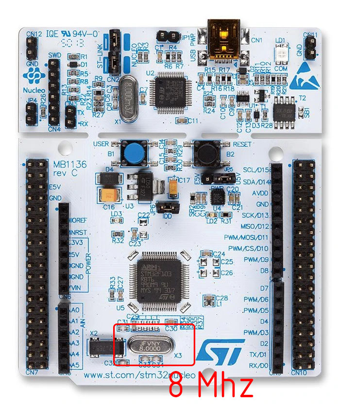
In good old days, when you wanted to run your AVR microcontroller at 8
MHz or 16 MHz, you simply put a crystal oscillator of that frequency.You
can look at a board and if the board has 16MHz crystal you became sure
that this board is running at 16MHz. Then you look at a 32bit ARM based
board and see it has a crystal of 8MHz, you cry deep in heart and wonder
why this poor microcontroller is running at the speed of a snail 🙁 Wait!
this is not true! This beast is not running at 8MHz! Here comes the first
new concept of this new domain, the PLL. The PLL stands for phased lock
loop. Wait, wait, wait! Don’t get scared of this term! From your point of
view, that is a software developers point of view this is a very simple
thing which multiplies the input frequency and makes it large. So in all
ARM based hardware you will find small value crystals like 8MHz or 16MHz
etc but actually they are running at much higher frequencies by the help
of their PLLs. An STM32F0 based board usually runs at 48MHz using a 8MHz
crystal, which is 6 times the crystals frequency. Similarly STM32F1 series
MCU runs at 72MHz by multiplying its 8MHz crystal frequency by 9 times.
More details about PLL and clock configuration would be done in its
dedicated article.
Two Buses
In simpler 8 bit world, while developing software we didn’t cared about
the bus much. I hope you know what a bus is. A microcontroller is a single
chip device which includes a CPU (central processing unit), the memory
(RAM, FLASH etc) and peripherals (like TIMER, ADC, RTC etc). The bus
connects the CPU with the memories and also with the on-chip peripherals.
A basic knowledge of this bus system is required for becoming successful
ARM developer.
First key concept here is that ARM based microcontrollers generally do
NOT have a single bus, but they has few different types of bus on the same
chip for different purposes. Here I am giving a very brief information on
this subject. Basically their are
two different types of buses.
One of them connects the CPU to memories and this bus runs is fastest in
the chip. Another type of bus connects CPU to the peripheral, this bus may
be slower than the previously discussed bus. The commercial name for the
first bus is
Advance High Performance Bus (AHB). Some MCU uses a
lighter version of this bus called AHB Lite. The second type of bus is
called the
Advance Peripheral Bus (APB). In some microcontrollers
like the STM32F1 series, their are two APBs called APB1 and APB2. The APB2
is slower than APB1.
Peripheral Clock
Generally in ARM based microcontrollers clock signal from the oscillator
is NOT directly fed to the peripheral, they are “gated”. In other words,
all peripherals are in sleep because they do NOT receive any clock signal
unless you enable it.This is mainly done to increase the power efficiency.
So the first step to use any peripheral is to enable clock signal to it.
Then only that peripheral wakes up and starts working. Only after a
peripheral’s clock is enabled, you can read and write its registers. As
this article and the subject is target for experienced developers, I would
not discuss what a register is. All experts must be know it that it is the
standard method by which a peripheral and CPU communicates with each
other.
DMA (Direct Memory Access)
DMAs were not present on most 8 bit MCUs, but are basic feature in 32 bit
world. Even the cheapest and smallest STM32 MCU have DMA support. Its
absence in 8-bit world makes programmers get scared with this new jargon.
But no need to wory, you don’t need to use DMA in all projects. Only very
advance projects require use of DMA.
Alternate Function Remapping
Hope you all know what an alternate function of io pin.Most of the pins
of the microcontroller are dedicated for input output. From these pins
only the microcontroller gets connected with the outside world. In AVR
microcontrollers these pins were grouped in ports like PORTA, PORTB etc
and pins were named like PA0,PA1 etc. These were the general purpose input
output pins. But they also have a second function associated with some
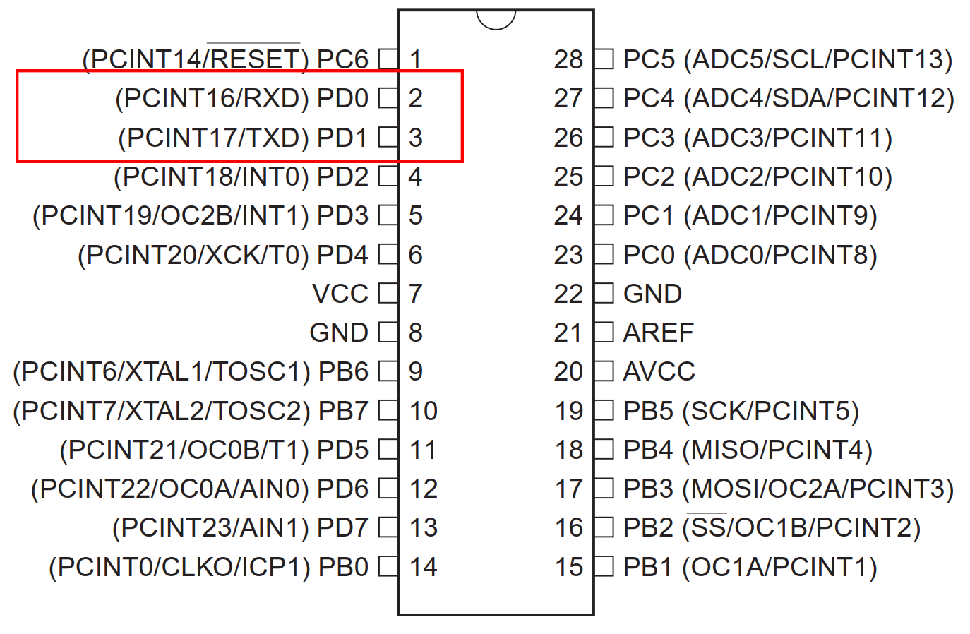
peripherals, say like a USART peripheral have pins like TX and RX. The RX
and TX pins are not separatly available but are shared with the previously
discussed general purpose input output pins.In the image below you can see
that USART peripheral’s RXD and TXD pins are shared with GPIO pins PD0 and
PD1 respectively. So the RXD and TXD are the
alternate functions
of pin PD0 and PD1 respectively.
Now in STM32, number of peripherals is very high, and peripherals are
sophisticated too, requiring more pins. AVR microcontrollers do not
support handshaking function in hardware but STM32’s USART does, so for
each USART in STM32 there are not only RXD and TXD pins but also CTS, RTS
pins. And there are not only one USART peripheral, even small 32 pin
device has two USARTs. So it is not possible to map every pins of every
peripheral present in the chip to external pins. So each GPIO pin has more
than one alternal functions and the user has the choice and freedom to
select the alternate function she/he needs. Let is make it clear with a
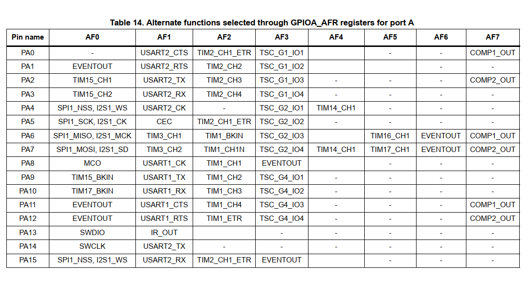
practical discussion. The device of reference is
STM32F051xx which
is a ARM Cortex M0 based MCU, available in 32,48 and 64 pin packages. In
the figure below (taken from device datasheet page number 37) you can see
that each PORTA pins can have up to eight alternate functions from AF0 to
AF7.

Hello Avinash,
Nice to see an article from you after a long time. Hope all is well with you.
Do we expect more articles on the STM32 from you?
Take care.
Deepak Nair
Yes, I will update more article on the series.
Good article, i start think about ARM.
Thank you Mr. Alex, hope you also like our future articles.