In this turorial we will see how we can easily interface a 24C series serial EEPROM with AVR microcontrollers.
What is an EEPROM?
An EEPROM is kinds of novalatile memory, that means it is used for storing digital data permanently without any power suply. EEPROM stands for Electrically Erasable Programmable Read Only Memory. The advantage of these kind of ROMs is that they can be erased Electrically to make them ready for storing new data. Compare this with a CD R disks they can be recorded only once. A small amount of EEPROM is also available internally on the AVR chips. So if the volume of data you want to store is small (say few user names and password) then you can use it. The internal eeprom makes design small and simple.
But if the amount of data you want to store is large, say in order of few tens of kilobytes then you have to interface a External EEPROM chip with your AVR MCU. You can store pictures, sound and long texts in these eeproms.
Their are many kinds of EEPROM chip available from many manufactures. One very common family is 24C series serial EEPROMs. They are available upto 128KB in size. They uses I2C interface with host controller (MCU) which is a very popular serial communication standard. I will write more indept tutorial on I2C in comming days and in this tutorial I will give you easy to use function that you can use without any knowledge of I2C interface.
In this tutorial we will be using 24C64 EEPROM chip which has 8192 bytes = 8 KB = 8×1024 bytes of data storage.
The chip has storage location which have their unique address ranging from 0-8191. Consider these as storage cells so while storing and retriving data you have to tell the chip which cell location you want to read.
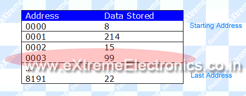 |
Fig. : Storage Cells inside the 24C64 EEPROM Chip. |
For exaple if you read location 0003 you will get 99 (see image above). Note each cell can store 8BITs of data so range you can store is 0-255 (-128 to +127). So if you want to store bigget data like int you have to store them in two cells.
Hardware Setup
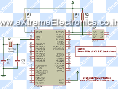
Connect your ATmega32 with 24C64 chip as shown in the circuit diagram. You can use any avr development board for the purpose or assemble the whole circuit in a Breadboard or Veroboard.
Fig. : Circuit Setup for 24C64. |
Software Setup
Download and add the following files to your AVR Studio project. Now you can use the following functions for EEPROM interfacing.
- 24c64.h
- 24c64.c
| EEOpen() |
Arguments – None Returns – Nothing Description: This function should be called before any read/write operation. This functions initialize the communication channel. |
| EEWriteByte(unsigned int address,uint8_t data) |
Arguments
Returns
Description: Use this function to store a 8bit value in any EEPROM storage cell. |
| EEReadByte(unsigned int address) |
Arguments
Returns
Description: Use this function to read a 8bit value from any EEPROM storage cell. |
Sample Program.
The following sample program demonstrate the use of external EEPROM interfaing functions. The program makes use of the LCD library for AVRs to display information in a 16×2 LCD display. The program first writes 8Kbytes of data to a 24c64 eeprom to fill the whole eeprom with ‘7’ and then it reads back to see if all the location has 7. If the condition is met the screen shows "Write Successfull" message.
I have used my xBoard – An Advance ATmega32 development board to test the routines. You can use any devboard with ATmega16 or ATmega32 MCUs. The 24C64 was mounted on a Breadboard.
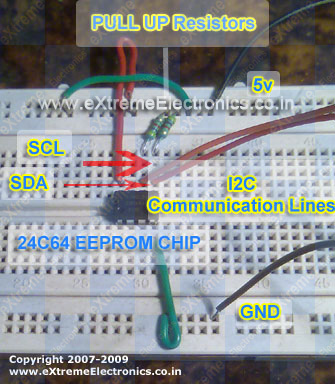 |
Fig. : 24C64 Serial EEProm Interface with ATmega32. |
The 5v,GND,SDA,SCL were connected to the xBoard development board.
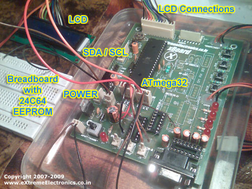 |
Fig. : xBoard with MCU ATmega32. |
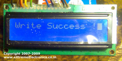 |
Fig. : Output of 24C64 test program. |
/*

A sample program to test the Extrenal EEPROM interfacing

routines. The program fills the whole EEPROM with 7 and
then reads the whole EEPROM memory to see if all of them
contains 7.

This helps in quick testing of you hardware /software before
using these routines in your own programs.

The target for this program is ATmega8, ATmega16, or ATmega32
running at 16MHz. If you use slower crystal the program will
simply run slow but without any problems.

This program also makes use of eXtreme Electronics 16x2 LCD
Interfacing routines. See the related page for more info

Author : Avinash Gupta
Date : 16 March 2009
Mail : me@avinashgupta.com
Web : www.eXtremeElectronics.co.in

NOTE: IF YOU USE THIS LIBRARY IN YOUR PROGRAMS AND FINDS

IT USEFUL PLEASE MENTION US IN CREDIT AND RECOMEND OTHERS.


*/

#include <avr/io.h>
#include "util/delay.h"

#include "24c64.h"

#include "lcd.h"


/**********************************

A simple delay routine to wait
between messages given to user
so that he/she gets time to read them

***********************************/

void Wait()
{
   uint8_t i;

   for(i=0;i<100;i++)
      _delay_loop_2(0);
}

void main()
{
   //Varriables
   uint8_t failed;
   unsigned int address;

   //Initialize LCD

   LCDInit(LS_BLINK);

   //Init EEPROM
   EEOpen();

   _delay_loop_2(0);

   LCDClear();
   LCDWriteString("External EEPROM");
   LCDWriteStringXY(0,1,"Test");

   Wait();

   LCDClear();
   LCDWriteString("Writting...");

   //Fill whole eeprom 8KB (8192 bytes)

   //with number 7
   failed=0;
   for(address=0;address<8192;address++)
   {
      if(EEWriteByte(address,7)==0)
      {
         //Write Failed

         LCDClear();
         LCDWriteString("Write Failed !");
         LCDWriteStringXY(0,1,"Addess = ");
         LCDWriteInt(address,4);
         failed=1;
         Wait();
         break;
      }
   }

   LCDClear();

   if(!failed)
      LCDWriteString("Written 8192bytes");

   Wait();

   LCDClear();
   LCDWriteString("Verifying ...");

   //Check if every location in EEPROM has

   //number 7 stored
   failed=0;
   for(address=0;address<8192;address++)
   {
      if(EEReadByte(address)!=7)
      {
         //Failed !

         LCDClear();
         LCDWriteString("Verify Failed");
         LCDWriteStringXY(0,1,"Addess = ");
         LCDWriteInt(address,4);
         failed=1;
         Wait();
         break;
      }
   }

   if(!failed)
   {
      //We have Done it !!!

      LCDClear();
      LCDWriteString("Write Success !");
   }

   while(1);

}
Note On Installing 16×2 LCD Module.
The LCD Module can be easily installed with AVR ATmega32 as the sample program supports it. The connection is simple. Connect the LCD to your ATmega32 as shown below. For Finding out location of PINs such as PC7,PC6,PB4 etc see the ATmega32 datasheet. The LCD must be installed to see the output of the program. After powering on the circuit please adjust the 10K POT until the display is clearly visible.
I strongly recommend you to see the LCD Interfacing Tutorial and Setup and run some LCD demo code to be sure that LCD is working correctly.
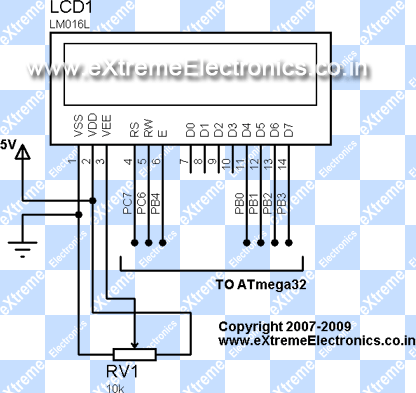 |
Fig. : LCD Interface with ATmega32. |
Downloads
All the required files for 24C eeprom interfacing with AVR MCUs.
Facing problem with your embedded, electronics or robotics project? We are here to help!
Post a help request.



Hi Avinash,
I am thinking of ATMega16 to use for sending data to a transmitter for testing purposes. Should I use EEPROM to store the data to be sent or can I just directly write the data in program and it randomly stores and sends it? And is there an easy way to do it for big data (for ex. with arrays) or should I do it byte by byte?
Hello Fortune,
🙂
You can use a EEPROM such as 24C64 (8Kbytes) or 24C1024 (128Kbytes) to store that data. Read them byte by byte in loop and transmit. I think 128K byte of data would be enough.
Hi Avinash,
Thank you very much.I really appreciate your effort and help!
Hi look your email to see my lib
Waht about if you don’t have SCL SDA Port, for example
if We need maybe PB5 and PB6 (without TWI register)?
best regard and thanks for nice work
I just need to output 256bytes. I need to output them serially. I have just thought to write it in the program in a loop using if the corresponding bit is 1
if(data[i]&(1<<n)) //n is the current bit # in progress
PORTA|=(1<<output);//output is the pin used for serial comm.
is this correct and enough? do I need a delay between every bit/byte? and what will be the baud rate(ATMega16) as default if i dont do any init.? (I want Baud ca. 1Kbit/s)
Hi,
What is the value of the resistors connected to the 24c64.It
says 4k7.What does that mean?
@Fortune,
You have a lots of confusion. First you are manualy sending just bit by bit to a port. In that way you cannot do RS232 communication. No device (such a PC) will be able to make anything out of that varrying voltage on a PIN.
Their is a STANDARD for RS232 communication.
You are talking about BAUD rate and you are NOT AT ALL USING THE USART. The baud rate is assosiated with USART.
and 1Kbit/s is not a standrad baud rate.
PLEASE GO THROUGH THE SUBJECT BEFORE ASKING.
SEE
https://extremeelectronics.co.in/avr-tutorials/rs232-communication-the-basics/
@Mozard
4k7 = 4.7k = 4.7 Kilo Ohms = 4700 Ohms
Got it
its just a standard way in commercial electronics!!!
Remember that from now.
Hi Avinash again :),
first of all I dont want to send the data using RS232 but via a normal port like portA. I said serial comm. technically while I will send them bit by bit using just one pin of a port.
I may have used the baud rate wrong but I wonder to know in what freq. I output the bits in the Port? As I know default freq. of ATMega16 is 1Mhz, but my output freq. will be less than 1MBit/s while one output op. takes more cycles than 1???
Sorry for putting on too much confusion..
Hi Avinash,
I am trying to read data from a file and then store the data in the 24C64.Do you have any idea how this could be implemented? I am trying to use fopen for file reading, but it is not working.Any help would be appreciated.Thank you..:)
Hi everyone,
I need some help with I2C protocols. I want to store my program in an external I2C Memory AT24C512, and execute the program from there.
But i am clueless on how to go about, i know about the i2c read and write cycles
AVR MCU does not support execution from external memory.
One way you can go is to write a bootloader that first loads the program form external memory to internal flash then start execution. See datasheets
actually i am working with 8052. can you give me some suggestion for i2c interface with 8052.
thank u
Hello Avinash, I saw your code you are doing interfacing LCD with Atmega32. Was wondering if you help me to get started with Interfacing EEPROM(25AA1024 I/P ) and Real Time Clock (DS1305) with ATmega32 using 3-wire SPI. I did all the wiring on breadboard let me know if you want to know which pins i am using.
Thanks
cheers,
Romil
Did you do it?
hi
iusing eeprom in rfid project with 1mb (sst25f016b)interfacing to atmega32using spi and ineed ur help to start cod
Hello Avinash,
There is very valuable notes on AVR microcontroller. I started with ATMEGA8 and I connect it with external crystal oscillator, of 8 MHz, but I think it is work on internal oscillator. I search for that then i found that thee is a fuse bit, please tell me about fuse bit ant how can i programme fuse bit. At present i use AT-PROG ( Parallel port, with two resistors directly connected to IC).
Thanks
Kapil
Fuse byte info here
http://forum.extremeelectronics.co.in/viewtopic.php?f=2&t=24
hi, i am trying to interface atmega 16 with at8052, where 8052 is the master which is connected with RTC(DS1703) ATmega16 is a slave i am not able to interface ATmega16 with AT8052, there is some problem in slave coding, please can you help me in coding of ATmega 16 as a slave mode ,
hi avinash..
I am using 24C04. I modify address limit as 4096. I am using your I2C library with ATmega32. My program is running upto lcdstring(“Writting…”). But its not running or somewaht else after this. I didnt used 4K7 pullups are they very necessary. Plz Clarify
@Devesh
Yes in I2C pullups are required. Without it it won’t work
hi…
What should be the DDR values for PORTC as we are using SCL & SDA.
It didn’t work with proteus 🙁
anyone knows why???
It gets stuck in the command writting…
In proteus u have to remove two pull up resistors (4.7K)
but in real case use them
thanks Avinash,
I already tried that,
but even so, it didnt work 🙁
can you help me on this…
hi avinash..
I am using AT24C04 what kind of modification i should do in your code to make it compatuble to 24C04.
@Devesh,
Use without any modification
hi avinash,
thats a good tutorial
i want to interface atmega 16 with eeprom, but only on avr studio first, also i need to store 120K data on it, can u help me in it, as in which eeprom better, which ports of eeprom connected to scl,sda for i2c and more
@Kushal
use 24C1024 EEPROM it has a capacity of 128KB
Hi Avinash,
I have a couple of questions
1) I want to transmit data bit by bit to flash memory and store it in an empty array. I already have used your tutorial on RS232 and I have got data transmitting.
But I can’t get it to store in the appropriate array. Should I use a buffer, like in EEPROM or something or should I store it directly.
The transmission rate is not a problem for the project im using it for.
Thanks
Hi Avinash,
Wikipedia says in their I2C overview that each slave on the I2C bus has an address and in turn there could be multiple slaves connected to the bus. How do I set or learn the address of the 24Cxxx chip? And how to connect if I want to have more than one of these eeproms attached? How do I address them?
Thanks
@Michal,
Very good question. Yes thats the beauty of I2C bus. Each slave on it have a unique address, thus many slaves can be connected in parallel in same bus lines. the address in I2C bus is 7 bit (the last bit is Read/Write select bit) so as many as 128 I2C slave can be connected in i2c bus.The 24C series has the address in form of [MSB]1,0,1,0,A1,A2,A3[LSB] where A1,A2,A3 can be set to proper state by using 3 pins on the chip. So as many as 8 24C eeprom can be connected in a bus.
In the above example I have not connected A1,A2,A3 (this means the are 0, 0, 0) to keep it simple. For more details see data sheet.
Hi Avinash
very good effort ,i want to make one master(atmega32)read & write with 3 slaves (atmega32), how can i send and recieve data from them.
Dear sir, if possible please provide tutorial on interfacing micro Controller, with other micro controller using I2C/ twi,
@sridhar – what you probably need is a multi-master i2c setup where each MCU can asynchronously send data to any other i2c device on the bus. Google for “i2c multi-master” and you’ll get a number of useful links.
@mohamed – do you mean 3 ICs writing into the eeprom and one IC reading it? In that case you’ll probably need multi-master as well.
Both of you guys could get away with just one bus master but then the setup would need an interrupt line from each slave, alerting the master that there are data to be processed. The master will then issue a read command to the slave, fetch the data and process. It really depends on what you’re trying to achieve. Whether to choose single-master or multi-master depends on circumstances.
@Michal
Thanks for helping out Sridhar 🙂
i make wide search but i didnt find interfacing two avr ,i find avr with another devices such as eprom,could u Nominate me web site
thank you 4 all for helping out,
here i am using single-master, i.e one master need to read multi slave, but all the slave is of same Atmega 8 as well as master,
ya, iam trying on google but links are not helping out much.,
if any one tried the same please help me out.
thank you for ur caring,
what i want to do is only one master(atmega32)read & write with 3 slaves (atmega32)
hey guys where r u???????
If we says A1,A2,A3 are used to unique address makeing:
1. only in 24c01,24c02 -> 8 IC’s
2. 24c04 has two pages switched by A3 -> 4 IC’s
(simply you can without changing code change 1*24c04 into 2*24c02)
3. and go on….
thank you for your web.but i dont know how to connect thw wire to real lcd.because in real lcd we have 16 socket.but in diagram lcd we have 14.please help me.thank
@Ali
The PCB of the LCD has the PIN names. From that you can clearly see that the last two pins 15 and 16 are connected to the LED backlight !!!
hi avinash
amazing tuts !!!!!!!
i want to store a set of words in eeprom . as per your file it enables the storage of only int datatypes. can i store strings by just changing the datatype of the argument in the functions. or shld i make anyother change
Dear sir,
I am using AVR micro controller, atmega 16, in need to communicate TWi interface with other micro controller,
I am using code vision for the complier.
I tried the code which is given in atmel application 311,312, etc but it was not working may be I could not properly analyze,
So, I built the RTC interface for DS1307 it was working with the Code vision in built library , so I have taken only the read format of the RTC and I tried to implement the slave,
With
START();
Write address();
Start();
Write location();
data=read data();
Return data;
By this code I was able to get data from the RTC,
So I thought to go with reverse engineering/programming to send a data to the master as the slave microcontroller need to act as RTC for only this particular code, but still it is not working,
Please if u have any such general implication of the i2c master and slave code please help me,
Hi Avinash!
Your EEPROM libraries are awesome! I am new to AVR’s though I have worked in PIC n 8051! But from scratch I could learn AVRs in a week!!! Thanks to all your efforts to build code libraries and projects that teaches a novice end to end in a short span of time!!! All the contents you have given are so useful, that I am working on a product with all the support libraries and schematics you have furnished in your site.
hi,
i tried reading RTC registers after every 1sec but it fails to update time on LCD. At power on-reset only once it display the time but after it is not updating time. Please help me.
thank u
hi avinash!
great tutorial, now i want to interface EEPROm with LPC 2148 controller can you help me for that?
hi i’m vinod a final b.e student .i’m using a 24c32serial eeprom in my project iwant to know whether the eeprom cn erased by using code if so can i get what instructiona to be used
dear avinash ,
i have gone through ur code and its working fine. i have one doubt that why u have used a dummy writing sequence inside the function readbyte().
and one more doubt isi have written 0x0A address with some value but all locations including 0xA0 shows the same value. what is the reason ?
plz reply me soon.
See 24Cxx datasheet. It is required .
its there in your code. if anything wrong plz send me the exact code. my id is paltu4u@gmail.com
Thanks my frind
Thank for this Library, i using it on my projects.
Here is I post your library with comments on russian on my own site.
http://avrlab.com/node/84
@AVR Lab
You have not provided any link to the original source?
Please provide a link to this page.
Pingback: Interfacing external memory with avr
hey av,can i just use 24c128 eeprom with your functions.i mean are the functions built for only 24c64 eeprom or for all 24cxx series eeprom?
Thanks for this wonderfull turorial , I am working on project where my IO is very limited, this is perfect as I will be storing a large structure in the memory which wont change that often so E2 is perfect for this.
Pingback: Software I2C Library for AVR MCUs | eXtreme Electronics
Hi Avinash,
Thank you so much for nice tutorial and I subscribe your web also.
Regards.
Mr.P
How about interfacing LCD using I2C with ATMEGA32??? Can you enlighten me on that
Thanks for your tutorial and code ! Its wonderful and helpful and I was able to simulate in proteus successfully !!! But with CPU and crystal frequency set to 16 MHZ, I get a statement
I2C MEM TIMING: start setup time violated.Clock positive edge was at 223.29m Hold time is 4u minimum hold time is 1.25u
and similarly
I2C MEM TIMING: stop setup time violated.Clock positive edge was at 223.396m Setup time is 1.25u minimum time is 4.7u…
But if the same simulation is executed with 4MHz clock frequency set those statements are elimnated…. The final output is obtained in both the frequencies… but my questiion is how does this happen??? when u r CPU frequency changes SCL frequency also changes but the data transfer is taking place in both the cases.. please enlighten me… asap !!!
the cpu does cycles of code in chucks every clock cycle
much like a bus picking up people
if theres to much it will run more empty then full and drop code unless u program for it cpu has no ai to make most of its time and data
if its mostly empty then it will just keep doing its cycle anyway with air people like air gitar this is wat null data is
i bet the code has been made to reflect cpu speed sos ur sending data at wrong way to wat eeprom needs
by looks ur not waiting long enuf for the eeprom to respond its minaum is 4u seconds sos it will not answer u till after 4u has passed
but ur code is only waiting 1.25u sec sos its already gone
reading the code and not being smart with all this the code runing at slower speed doesnt need wait cycles or to think about how long each comand takes to get job done
basicaly the slow speed alows for less code to be made every think runs esayly
so u going to have to add delys to that code or increase the time taken to compute a instruction or make the code halt for a reply is ideas
theres no simple answer or simple problem
unless you are to forget to learn the how to aproch
and learn the coarse and affect princaples learn why and not how
im only just starting on mcu most code ive done is bat files and runing dos but im finaly starting to click
i sageust u start with hex if u wana learn it will give u more power and more deepth understanding but takes way more efort to use XD
program halts at “Writing”…copied the exact program and ran the simulations in proteus.
Anyone knowing the reason?
I’m using an ATmega8 dev board running at 16 MHz and I thought it got stuck at “Writing…” as well but after about 2 or 3 minutes I see “Write Success!” Just took a long time to fill all data I guess or check that your uCntlr clock frequency is correct.
I’m using your library . When I’m trying to write ascii value 65 at 0000 , then 67 at 1 it is writing 67 at both addresses , ie the data I’m writing later , is over written in all the addresses.Why it is happening please help me.
Regards
Bikash
Post your code in the forum
/*
* i2ctest.c
*
* Created: 7/24/2012 5:39:06 AM
* Author: Bikash
*/
#include
#define F_CPU 16000000UL
#include
#include “24c64.h”
#include “lcd.h”
void delay()
{
for(int i=0;i<2;i++)
_delay_ms(100);
}
int main(void)
{
lcd_init(LCD_DISP_ON_CURSOR_BLINK);
lcd_clrscr();
lcd_puts("Welcome I2C");
uint8_t valu1,valu2;
char c;
EEOpen();
delay();
lcd_clrscr();
if (EEWriteByte(1,65)==1)
{
lcd_clrscr();
lcd_puts("Write at 1 Success");
delay();
}
else
{
lcd_clrscr();
lcd_puts("Write at 1 failed");
}
if (EEWriteByte(0,67)==1)
{
lcd_clrscr();
lcd_puts("Write at 0 Success");
delay();
}
else
{
lcd_clrscr();
lcd_puts("Write at 0 failed");
}
valu1=EEReadByte(0);
lcd_clrscr();
lcd_puts("Value1=");
lcd_puts(valu1);
lcd_gotoxy(0,1);
_delay_ms(100);
valu2=EEReadByte(1);
lcd_puts("Value2=");
lcd_puts(valu2);
while(1);
return 0;
}
Its displaying C ,ie 67 in lcd for both the values . I've not made any changes in your 24C64 code files.
Regards
Bikash
@Avinash : I’ve not got yr reply sir. Hav u solved the problem ?
Regards
Bikash
@Bikas
Try this code
/*
* i2ctest.c
*
* Created: 7/24/2012 5:39:06 AM
* Author: Bikash
*/
#include
#define F_CPU 16000000UL
#include
#include “24c64.h”
#include “lcd.h”
void delay()
{
for(int i=0;i<2;i++)
_delay_ms(100);
}
int main(void)
{
lcd_init(LCD_DISP_ON_CURSOR_BLINK);
lcd_clrscr();
lcd_puts("Welcome I2C");
char valu1[2];
char valu2[2];
valu2[1]=valu1[1]='\0';
char c;
EEOpen();
delay();
lcd_clrscr();
if (EEWriteByte(1,65)==1)
{
lcd_clrscr();
lcd_puts("Write at 1 Success");
delay();
}
else
{
lcd_clrscr();
lcd_puts("Write at 1 failed");
}
if (EEWriteByte(0,67)==1)
{
lcd_clrscr();
lcd_puts("Write at 0 Success");
delay();
}
else
{
lcd_clrscr();
lcd_puts("Write at 0 failed");
}
valu1[0]=EEReadByte(0);
lcd_clrscr();
lcd_puts("Value1=");
lcd_puts(valu1);
lcd_gotoxy(0,1);
_delay_ms(100);
valu2[0]=EEReadByte(1);
lcd_puts("Value2=");
lcd_puts(valu2);
while(1);
return 0;
}
Thank You. Let me try.
Thank you can you please tell me what was my fault ?
Regards
Bikash
@Bikash
Tell me whether it worked or not?
Ya it worked.
I tried the EEPROM write and verify code.
It whows write error at address 0000 and.
verify error at address 0000.
I checked all the connections.
Can any one guess probable error.
@Raoof
Please purchase ready made development board as shown in the article to do the experiment! We cannot help debug your hardware!
That’s a simple and wonderful tutorial…
Thanks a lot…
Pingback: Getting Started with Microcontrollers | eXtreme ElectronicseXtreme Electronics
Pingback: SIXTEENTH DAY OF MY SIX WEEKS TRAINING | nagpalnaina1658
Hi,
I found this article very useful in testing ATmega8 TWI interface with EEPROM 24C04.
Thanks.
Regards,
Karthik
can we use proteus to simulate it?
Hi. Could you please show how to use a SPI EEPROM, for example AT25256 ?!!!
I am trying to use the Atmel 24C1024B EEPROM with AVR ATmega16, can anyone please tell me why is 12 ms delay required after stop command in “write byte” function, this is unnecessarily taking too long a time during write operation, can it be made faster?….thanks……arun
Pingback: AVR SwimWatch 0.1 | My DIY Electronics Projects
Hi Avinash Sir,
am using 24c02 EEPROM, it has 32 pages of 8 words each, What sort changes i have to do in the code?
I have tried running the exact functions but unsuccessful, pull upresistors used on my devlopment board are of 14.8Kohm value
Great article
Could this be used to read from an SD card over SPI and output to the target eprom over I2C?
if you give us as code by using Code Vision AVR it will be good for us.
Great article!
I tried simulate it using proteus and it works.
could you please give us a code using CodeVision AVR?
thanks
hey sir, I tried to disconnect the eeprom but the program didn’t display ‘failed’ section :
//Write Failed
LCDClear();
LCDWriteString(“Write Failed !”);
LCDWriteStringXY(0,1,”Addess = “);
LCDWriteInt(address,4);
failed=1;
Wait();
break;
it stuck on displaying “writting….”
please help!
Pingback: [AVR] programming at24c512 via atmel studio
Splendid! right to the point code inside the library.. Thanks!
Hi
I have read your article on Extremal Electronics and will help you to set up rom for my atmega16 microcontroller if possible guide
Thanks
I need code for
memory clear or memory reset of 24c08
with atmel 89c51
because I have nvram for photocopier that has 24c08
used to save counter of machine.
I need to clear that counter to zero.
thanks.
I simulated it in Proteus. It shows
write failed
address = 0001
verify failed
address = 0000
Can anyone say what the problem is?
When this program goes in read cycle it reads value then multiply by 7 so you see the verify fail. Same problem here
hello sir,i want to store int value in external eeprom how to do that. please help
thanks in advance
Hello Sir,
After compiling above programme i m getting erroe for eeprom chip header file that no such directory. please help
Thank you sir,its working great
I am using your libraries. It is working fine with writing cycle but when i read back it reads the value and multiply it with 7. For example at address 0010 value was 01 when i read the value received 07 same as when i write value 2 it reads 14. What is the issue kindly reply