Those how are building microcontroller based project for little long must have got bored with the good old character LCDs. Whether you are bored or your application require to present more data to the user in a better way, you need Graphic LCD. Character LCD Interfacing is quite easy so every one uses it, but when I comes to Graphic LCD you need a well written and powerful graphic library. Its not enough that you read the LCD datasheet and connect it your MCU and start sending data. Because the LCD just appears to be block of memory whose contents are directly visible on screen. The datasheet can only guide you how to access this memory. You just can’t do much by writing to the memory. The graphic library is a piece of software that has complex algorithms to render graphic primitives like line, rectangles, circles, images and more. It also helps load fonts and render text and numbers on screen. So it provide high level access to the LCD screen and applications can be written much more easily.
While I was researching for graphic library for the GLCDs, I found some but I was not fully satisfied by any of them. So I began to write a clean, powerful, portable and easy to use library that can handle sever different graphic LCDs and can be ported to many MCUs. In this article I will use a Graphic LCD which is based on common KS0108 type controller with AVR ATmega32 MCU. In future I will port the tutorial and library for PIC and ARM CPUs.
Introducing the JHD12864E Graphical LCD Module.
Their are several type of graphical LCD module in the market. In this tutorial I will introduce you to a common graphical lcd module that is easily available in most part of the globe. If you are in India I request you to buy one of these from our online store, in this way you can help us.
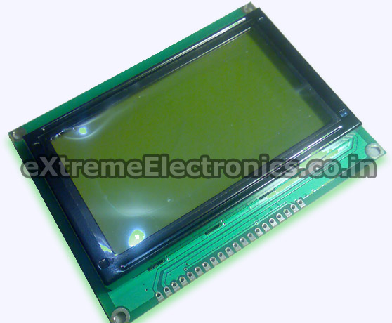
KS0108 based 128 x 64 Graphic LCD Module |
The specification of this LCD are as follows.
- 128 horizontal pixel and 64 vertical pixel resolution.
- Controlled based on KS0108B
- Parallel 8bit interface
- On board graphic memory.
- Available in Green backlight with dark green pixels.
- Also available in Blue backlight with light blue pixels.
- LED backlight.
- 20 PIN linear connection.
PIN Description
PIN |
Name |
Function |
Connection
with AVR PIN |
| 1 | Vss | Ground | |
| 2 | Vcc | +5v Supply in | |
| 3 | V0 | Contrast Adjust | |
| 4 | RS | Instruction/Data Register Select | PD3 |
| 5 | R/W | READ/WRITE SELECTION | PD6 |
| 6 | E | ENABLE SIGNAL | PB4 |
| 7 | DB0 | DATA IN/OUT | PC0 |
| 8 | DB1 | DATA IN/OUT | PC1 |
| 9 | DB2 | DATA IN/OUT | PC2 |
| 10 | DB3 | DATA IN/OUT | PC3 |
| 11 | DB4 | DATA IN/OUT | PC4 |
| 12 | DB5 | DATA IN/OUT | PC5 |
| 13 | DB6 | DATA IN/OUT | PC6 |
| 14 | DB7 | DATA IN/OUT | PC7 |
| 15 | CS1 | Chip Select 1 | PB0 |
| 16 | CS2 | Chip Select 2 | PB1 |
| 17 | RST | RESET SIGNAL | RESET |
| 18 | VEE | NEGATIVE 10V OUT | |
| 19 | LED+ | LED BACKLIGHT | |
| 20 | LED- | LED BACKLIGHT |
Graphic LCD Testing Circuit with AVR ATmega32
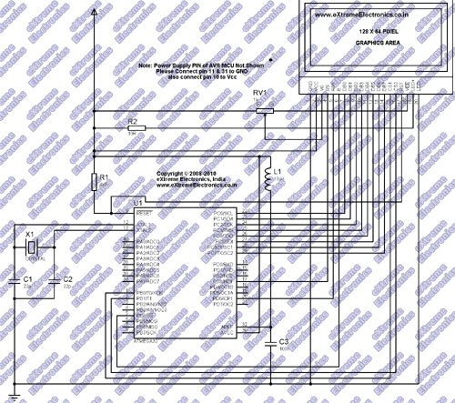
I suggest you to make a small circuit with ATmega32, its life support environment and Graphic LCD to experiment with these LCD. I have clocked the Test circuit with 16MHz crystal for maximum speed. Make the circuit as follows.
Schematic for AVR ATmega32 and Graphic LCD Connection. |
The RV1 (which is a variable resistor of 10K) is used to adjust the contrast of the display. If no display is visible on screen use this to adjust the contrast until you see everything clearly. The AVR’s Fuse bits must be set as follows to disable JTAG and enable external crystal.This step is very important and things won’t work if you forget this.
- HIGH Fuse = 0xC9
- LOW Fuse = 0xFF
Graphic LCD Test Circuit Fabrication Tips.
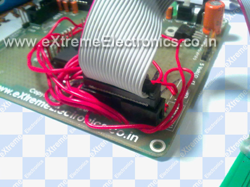
I have used my Low Cost 40 PIN AVR Development Board for quick testing. I is a bare bone AVR board with AVR and its life support. The nice thing is that it has prototyping area surrounding the AVR. I used this area to mount the 20 PIN FRC Box header for connecting the GLCD.
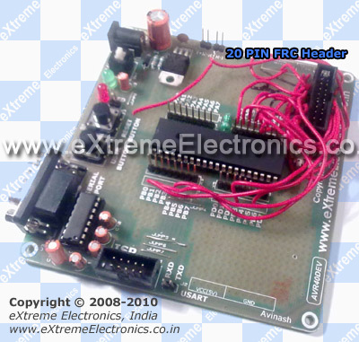 |
40 PIN AVR Devboard with Graphic LCD Connector. |
In the above image you can see the 20 PIN FRC Box header is soldered. The red wires connect the PINS of header to the MCUs I/O lines. They also supply power to the module and its led backlight.
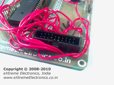 |
Graphic LCD Connector. |
Take a 20 PIN FRC Cable. It has female connectors at both ends. Cut it to half and solder the wires to 20 PINs on the LCD Module. The image below illustrate the point. Now you can easily connect and disconnect the graphic lcd module from board.
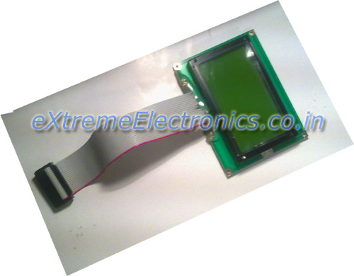 |
Graphic LCD with Wire Soldered. |
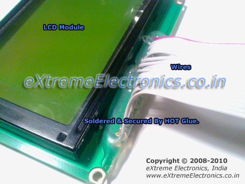 |
Graphic LCD with Wire Soldering. |
 |
Graphic LCD Connected. |
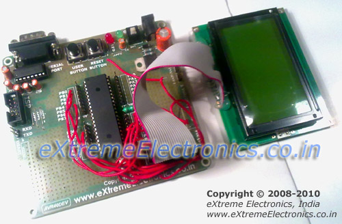 |
AVR Graphic LCD setup is ready! |
In the next tutorial we will get our hands wet by writing the "Hello World" App for the Graphic LCD. I will show you how to create a AVR Studio Project with Graphic LCD Support by Adding and Configuring our Solid Graphic Library for AVRs.
So don’t forget to subscribe to the RSS Feed or email delivery of new articles! See the sidebar for more info. You can also connect via Twitter.
I also wish all my Indian friends a very happy Independence Day! As I was writing this article on the eve of Independence day.
Other Parts of the Tutorial Series
- Part I – Introduction to GLCD and Hardware Setup
- Part II – Downloading and Installing ProGFX!
- Part III – Explains Graphic Primitive Functions.
- Part IV – Font and Text Handling Functions.
By
Avinash Gupta
Facebook,
Follow on Twitter.
www.AvinashGupta.com
me@avinashgupta.com
Facing problem with your embedded, electronics or robotics project? We are here to help!
Post a help request.



I am eagerly waiting for this article from a long time!
sir,can you please upload tutorial for generating custom characters(like degree symbol,smiley etc.) in a 16×2 lcd while using 4 wire lcd mode.
can u give more info about this with a video/…………..
Pingback: Interfacing Graphical LCD with AVR MCU - Part II | eXtreme Electronics
Pingback: Interfacing Graphical LCD with AVR MCU | eXtreme Electronics
Pingback: Using LCD Module with AVRs | eXtreme Electronics
Hello sir,
I had brought a Graphical LCD from your company.I want to make this project.But sir you use a coil in this circuit of Interfacing KS0108 based 128×64 Graphical LCD with AVR MCU project.But I can not understand this coil(10uH)is necessary in this project?Plz clear it it is necessary.I am waiting long time for this project.Plz help me.
Thanking You
@Manas Paul,
The 10uH Inductor is used as prescribed in AVR Datasheet to reduce the noise in ADC. If you do not plan to use the ADC you can omit it. They don’t cost more than Rs. 5-7 so using them is a good idea. I really don’t like bad designs so I include them in most of my designs. 🙂
Pingback: Handling Text and Fonts in ProGFX | eXtreme Electronics
Hello sir,
Thank U for the information.
I have a other question.I have seen your total project in graphics LCD in Youtube.There are some pictures.How you are include in your program.Can U give me a suggestion how I will do this.
Thanking You.
Hi
I am using a UC1698 and ATmega128. Please let me know which file I edit to change the port pins.
Your tutorial is excellent on GLCD’s
Thanks
Johan
@Johan,
Only works with KS0108 based LCDs and no pin change option available.
Pingback: Product Preview – AVR Graphical LCD Development Board | eXtreme Electronics
hello!
I really like the libary! I have a question, if I want to use AT90USB162 that can change the pinout? Because of this, IC the is portc incomplete.
Thank you the answer
Creative
“Only works with KS0108 based LCDs and no pin change option available.”
how no pin change option available.? isn’t it declared anywhere? I need to control with portG and use portA for data. Can you help me please?
@Ricardo,
PINS are declared on the driver source code but it is closed source so you cannot change it. If you need another pin mapping or different MCU just send me complete details and I will build the driver for that config. Ok
in the beginning,
GFX.org text appears for very long long time (53 seconds in Proteus) .
Please remove it or at least bring this value to a small no. of seconds
I need port c for some other purpose. Can you change your header file to port A?
will be thankful if you reply early!!
@Ek Ehsaas,
See Proteus simulation don’t run real time.
GFX.org appears for 53 seconds in proteus simulation :/
My hardware use the pins below, can you send drive for this pins. Can I write icon the size 48×48.
My Hardware
char GLCD_DataPort at PORTA;
char GLCD_DataPort_Direction at DDRA;
sbit GLCD_CS1 at PORTB2_bit;
sbit GLCD_CS2 at PORTB1_bit;
sbit GLCD_RS at PORTB3_bit;
sbit GLCD_RW at PORTD7_bit;
sbit GLCD_EN at PORTB0_bit;
sbit GLCD_RST at PORTD0_bit;
sbit GLCD_CS1_Direction at DDB2_bit;
sbit GLCD_CS2_Direction at DDB1_bit;
sbit GLCD_RS_Direction at DDB3_bit;
sbit GLCD_RW_Direction at DDD7_bit;
sbit GLCD_EN_Direction at DDB0_bit;
sbit GLCD_RST_Direction at DDD0_bit;
@Ronaldo,
Please also specify the MCU like ATmega128?
Also if you are using some kind of ready made development board, please specify.
Sir,
How can we display smileys or say write in Hindi on a simple 16*2 lcd using avr??
Thanx in advance,
Manan
Hi, I was wondering whether I could use the Avr Atmega644p chip or is it specificly Atmega32?
Thanx,
Armen
hi @Avinash, sorry my bad english, please i need some help, i need another pin maping, can you send me de lib with another pin maping?
data –> PORTB
E–>PA3
R/W–>PA4
RS–>PA5
CS1–>PA6
CS2–>PA7
thank you
ds_077@hotmail.com
@Ronaldo,
Please also specify the MCU like ATmega128?
Also if you are using some kind of ready made development board, please specify.
May 12th, 2011 at 6:35 am
Dear, sorry for delay to reply, because I received e-mail today.
I use atmega323L with my board.
Regards.
i’m using atmega324p
can you change the pin mapping for atemga323L for this configuration, if yes, how download it?
Regards.
data –> PORTA;
RS at PB3
CS1 at PB2
CS2 at PB1
EN at PB0
RST at PD0
RW at PD7
Hi sir,
can u give me the Graphic LCD(JHD12864E) Testing Circuit with p18f452 pic microcontroller
can u suggest any tutorial to interface camera module with atmega32?
Pingback: Analog Clock on GLCD – Drawing the Face | eXtreme Electronics
good day
firstly excelent tutorials, are helping me no end,is it possible to use any other ATmega avr with this code e.g 128a without alteration to code.
alex
@Alex,
No. It only runs on ATmega32
HIGH Fuse = 0xC9
LOW Fuse = 0xFF
—————–where and how can i set these values….plz tell/..
@Saumya
See this image
https://extremeelectronics.co.in/robotics/images/FuseByte.gif
See this article for details
https://extremeelectronics.co.in/avr-projects/pc-controlled-robot/
Pingback: Proteus model for JHD12864E
Pingback: About the graphic lcd, please help me!!
Pingback: features of GLCD JHD12864E.....?
Hi Avinash,
Any idea when you will restock the white backlight LCD (128×64) ? Its out of stock for atleast a month now.
Thanks & Regards,
Pradeep
hi sir, can you please send me the your library(libgfx.a)file in any readable format because i want to study that one and i am planning some complex programming with that.
Thanks
Ravi
@Ravi, No!
HEllo, i have the same PIN config, just the data port ist on port A. Can jou sent me the driver 🙂 PLEASE
luka.brinovsek@gmail.com
1 Vss Ground
2 Vcc +5v Supply in
3 V0 Contrast Adjust
4 RS Instruction/Data Register Select PD3
5 R/W READ/WRITE SELECTION PD6
6 E ENABLE SIGNAL PB4
7 DB0 DATA IN/OUT PA0
8 DB1 DATA IN/OUT PA1
9 DB2 DATA IN/OUT PA2
10 DB3 DATA IN/OUT PA3
11 DB4 DATA IN/OUT PA4
12 DB5 DATA IN/OUT PA5
13 DB6 DATA IN/OUT PA6
14 DB7 DATA IN/OUT PA7
15 CS1 Chip Select 1 PB0
16 CS2 Chip Select 2 PB1
17 RST RESET SIGNAL RESET
18 VEE NEGATIVE 10V OUT
19 LED+ LED BACKLIGHT
20 LED- LED BACKLIGHT
ON:
luka.brinovsek@gmail.com
@Lbrinovs,
Modification Charge is U$250
sir,
what is the 10R in the above schematic for GLCD…!ALSO the LC CIrcuit should be connected to AVCC instead of Aref which should be connected to GND via a 0.1 uf capacitor..am i right?
regards.
oh! sorry my mistake i misunderstood the schematic;its correct but can you please clarify what is this 10R Is it a resistor of 10k?
Hello Guys,
like everything in this world is paid, I find other free routines that do the same thing. I create sources for codevisionavr using Lcd vision
Also use the graphics routines Codevisionavr.
Send-me email and I will how to makea it.
hi will you please generate a lib ATmega16 for following pin mapping
rs—-PA0
rw—-PA1
EN—-PA2
D0-D7—PORTB
CS1—PA3
CS2—PA4
RST—PA5
i have purchased GLCD from your storebefore last two..
thanks
@Dhaval,
Modification charge is Rs. 2000/- for Indian Customers. Custom Startup Logo Extra Rs. 10,000/-
And what about having the black on white GLCD back in stock !!!!!!!!!
Hi,why when i try build i have error. I have instaled Avr toolchain and Win Avr. I use a avr studio 4. I have error:
C:\Users\EliteBook\Documents\Atmel\HelloGraphics\..\..\..\Desktop\ProGFX\include/gfx.h:441:35: error: unknown type name ‘prog_uint8_t’
C:\Users\EliteBook\Documents\Atmel\HelloGraphics\..\..\..\Desktop\ProGFX\include/font.h:15:1: error: unknown type name ‘prog_uint8_t’
C:\Users\EliteBook\Documents\Atmel\HelloGraphics\..\..\..\Desktop\ProGFX\include/font.h:24:1: error: unknown type name ‘prog_uint8_t’
C:\Users\EliteBook\Documents\Atmel\HelloGraphics\..\..\..\Desktop\ProGFX\include/font.h:26:1: error: unknown type name ‘prog_uint8_t’
C:\Users\EliteBook\Documents\Atmel\HelloGraphics\..\..\..\Desktop\ProGFX\include/fonts/arial12.h:46:16: error: variable ‘Arial12’ must be const in order to be put into read-only section by means of ‘__attribute__((progmem))’
../HelloGraphics.c:5:6: warning: return type of ‘main’ is not ‘int’ [-Wmain]
../HelloGraphics.c:11:4: warning: passing argument 1 of ‘GFXSetFont’ from incompatible pointer type [enabled by default]
Hey,
First I have to note that this has been a very helpful guide for me. Only Problem is the pin-configuration since I need some of the Pins you use for other purpose. Could you re-build it when i message you with the pin-configuration I prefer for my project? That would be awesome.
@Jabu,
We we can change the PINs but that would cost US$100.
hi .thanks
????
Sir what is the value of RV1??
in schematic it is shown 1K but in the article it is 10k???
I have interfaced the GLCD JHD 128×64 with Stellaris Launch pad, but I need some library files to draw and load images on to it.
http://www.npeducations.com/2014/01/interfacing-graphical-lcd-jhd-128x64e.html
nice tutorial
how to make this in proteus ks0108 is available there but how to check output?? no graphical lcd model is there. :/
Please reply soon
Please explain how to draw an image.
how to use the following function?
void GFXDrawImage(UINT8 x,UINT8 y,prog_uint8_t *img)
what exactly is meant by uint8_t*img ??
if there’s a tutorial related to this, give me link please!
Great tutorial. Thumbs up, man!
only thing i tried and couldn’t do was drawing my desired image. i downloaded bitmap converting tools but couldn’t get how to do that. I want my picture to appear on GLCD. Please let me know if it’s possible!
Best regards!
hi, how can i realize model of graphic lcd, i bought “Winstar wg 12864A” but i do not khow its model, and how to define it in bascom, thanks