Microcontrollers are good when it comes to brain, but to do anything in real world they need muscles too !
Their muscles are electromechanical actuators like motors.
Their are several types of motor available to do various type of motion. The simplest of them are DC motors. They can generate rotary motion and when wheels are attached to their shaft they can be used to move a body.
Applications include motion of a robot on flat surface like a floor.
Normally a DC motors runs at a high RPM, so to slow it down a gear head is attached in front of it. This makes RPM come down to values such as 50 RPM to 500 RPM. This also increase the torque online casino no deposit generated by the motor.
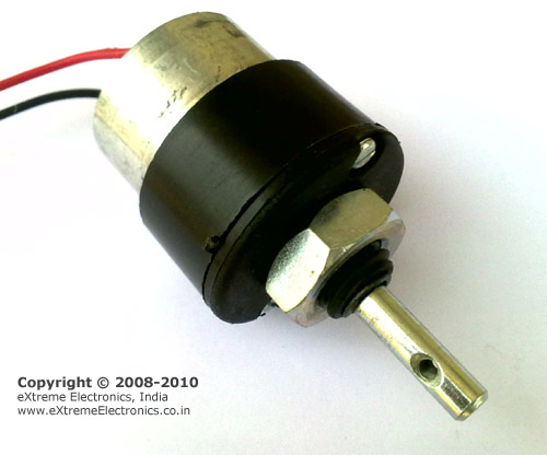
The image below shows a 12v DC Gear Motor. The front black portion contains the gear assembly.
| Fig. A DC Gear Motor |
In this tutorial we will learn the basics about these motors and how to control them using a microcontroller.
DC Motor Rotates in one direction when you apply power to its terminals. When you reverse the polarity of the supply it will rotate in opposite direction.
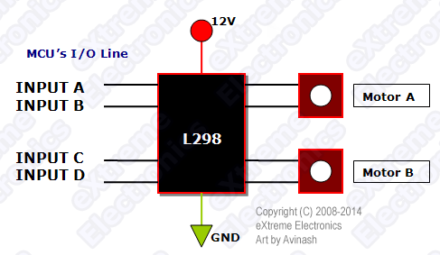
Since a DC Motor requires current in the range of 400ma to 1000ma we cannot supply them directly from the MCUs I/O Pins. We need some kind of driver circuit that can deliver more current to the motors. Also a MCU generally works off 5v supply but normal motors require a 12v (or 24v) supply. This circuit which is used to control a Motor from MCUs I/O line is called H-BRIDGE circuit. Many easy to use H-Bridge ICs are available, like the L293. One L293 IC has two H-BRIDGE circuits. So it can control 2 DC Motors.
 |
| Fig. L293 H-Bridge IC |
The Motor is controlled in the following way by MCU’s i/o lines
Motor A
- Clock Wise(CW) : Input A = High and Input B is Low
- Counter Clock Wise(CCW) : Input A = Low and Input B is High
- Stop: Input A= High and Input B is High
- Stop: Input B=Low and Input B is Low
Motor B
- Clock Wise(CW) : Input C= High and Input D is Low
- Counter Clock Wise(CCW) : Input C = Low and Input D is High
- Stop: Input C= High and Input D is High
- Stop: Input C=Low and Input D is Low
In this demo we will control only one DC motor. We will connect motor control inputs with our ATmega16 microcontroller in following manner.
| Name on Board | MCU’s i/o line | |
|---|---|---|
| Input A | IN1 | PC0 |
| Input B | IN2 | PC1 |
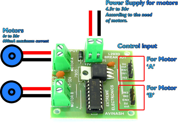
Introduction to the Motor Driver Board.
We will use our Dual Motor Driver Board to easily interface motors to out development board. It is built using the L293D IC discussed above.
| Fig. Motor Driver Board |
Since this is our very first motor control program, we will keep it simple. Thus we will not control the speed of motor from MCU, we will be just controlling is rotation direction.
But our motor controller board support speed control too. So we have to disable it first.
Speed control is achieved by sending PWM signals from our MCU to EN1 line. Similarly their is an EN2 line for motor B.
To disable speed control we need to tie EN1 line permanently to the 5v supply.
To do this take a two pin jumper and short EN1 line with 5v out line.
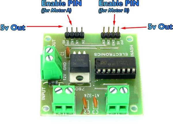 |
| Fig. EN1 and EN2 Pins |
Connection with the Development Board
Control Pins
| Dual Motor Driver Board | AVR Dev Board |
|---|---|
| IN1 | PC0 |
| IN2 | PC1 |
Power Input Pins
| Dual Motor Driver Board | AVR Dev Board |
|---|---|
| 12V | 12V Out (+) |
| GND | 12V Out (-) |
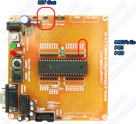 |
| Fig. Development Board’s Connection Points |
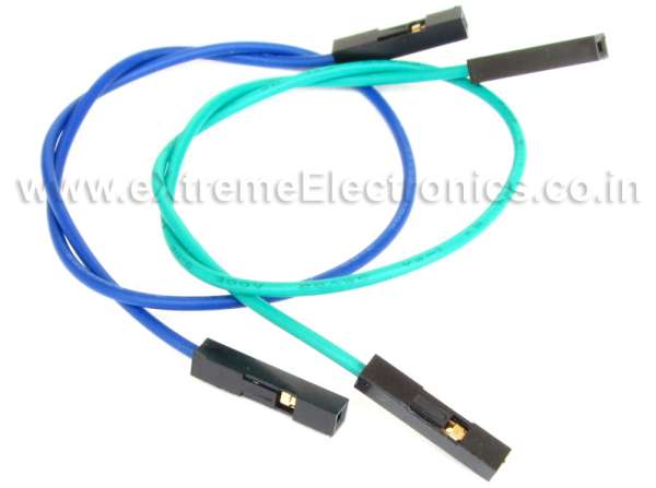
Control Pins can be connected using female to female burg wires.
| Fig. Burg Wires |
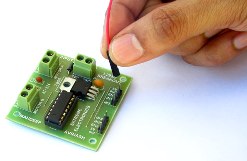 |
| Fig. Interconnection |
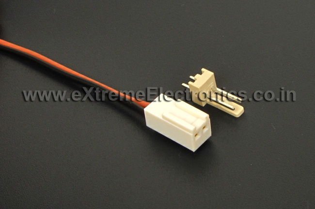
While the power input can be connected using the 2 pin relimate connecter. The female side is attached to two pin male connecter on the development board. While the wire side is peeled of a bit to remove the insulator and attached to the screw type connecter (green colour) on the dual motor driver board.
| Fig. Relimate Connecter. |
Now the complete ready setup would look something like this.
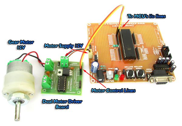 |
| Fig. Simple Single Motor Control using ATmega16 |
Download the precompiled hex file from the links given below and burn it to the development board. Power up the development board by using a 12V 2A adapter and switch on the board.
The motor will start rotating and after a few seconds it will change its rotation direction. Then it will stop for few seconds.
So now you have successfully learnt how control a DC motor with a ATmega16 microcontroller.
Videos
Downloads
- Pre-compiled HEX file ready to burn.
File Name: BasicSingleMotorControl.hex - Complete Atmel Studio 6 Project with source code.
Project Folder Name: BasicSingleMotorControl
Facing problem with your embedded, electronics or robotics project? We are here to help!
Post a help request.




Thank You , New tutorial after long long time, Wating for its speed control part,
@Mr. Uttam Dutta,
Thank you, yes more motor control tutorials will be published …
my motor driver ic is getting very heated when iam connecting load on the motor , the heat is sufficient for melting the plastic case of ic bed so i introduced new method which is by using IGBT irfz44n (Rs 8 eatch)it is not getting heated and it have a capacity of 40 amps,i thing it is better to use IGBT bridge to control the motors
hello . i’m fardin azadi . i’m engineer electronic . i want pcb and c files . please your send files .
thankyou .
i need your help to make pwm speed control motor using atmega16a
i need your help bro
sir, can you please tell how the speed of this dc motor be controlled using l293d and atmega16 microcontroller
how can i interface it with pid controller in matlab simulink.
Thanks for this usefull post.
i need to controll speed of this two dc motors separetly.
May you help me?
i am trying with bascom and proteus.