In this tutorial we will discuss a simple PC controlled robot. The Robot PC link will be a RS232 serial line. The robot will have only five commands.
- Move forward (RS232 char ‘F’ or ‘f’)
- Move backward (RS232 char ‘B’ or ‘b’)
- Turn Left (RS232 char ‘L’ or ‘l’)
- Turn Right (RS232 char ‘R’ or ‘r’)
- Stop (RS232 char ‘S’ or ‘s’)
To keep things as simple as possible, in this example we will use terminal software RealTerm for sending commands to the robot. Later on a dedicated software can be written on PC end to control the robot.
The Robot’s Hardware
The robot’s hardware will be a simple differential drive using two 200RPM DC Gear motor mounted on a HQ Metal Chassis with a front castor wheel. On the back motors we have mounted plastic wheels. More about differential drive is explained in this tutorial.
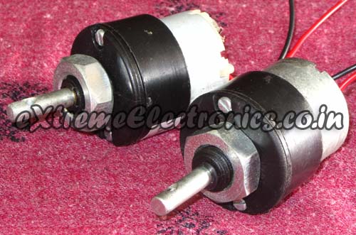 |
Gear Motors |
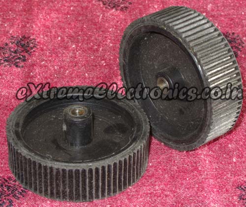 |
Wheels |
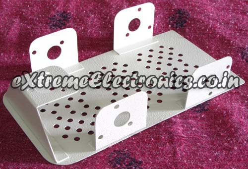 |
Metal Chassis |
 |
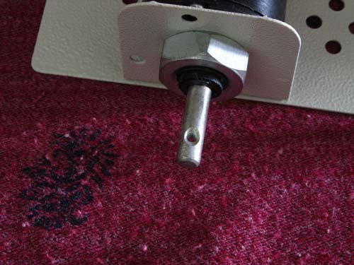
Remove motor’s nut |
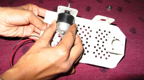 |
Insert the motor |
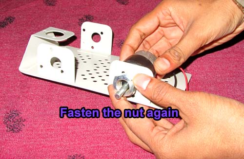 |
Fasten the nuts again |
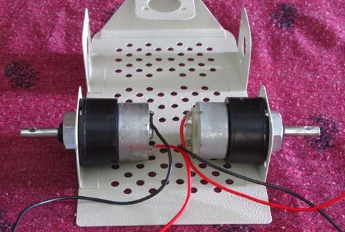 |
Both motors installed |
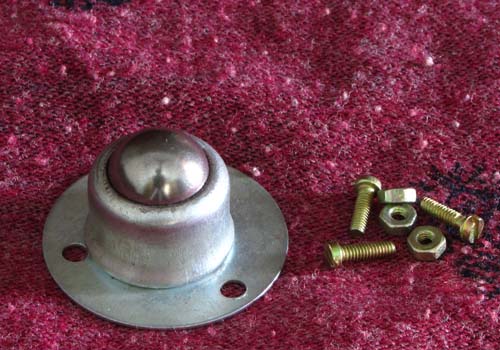 |
Front Castor wheel |
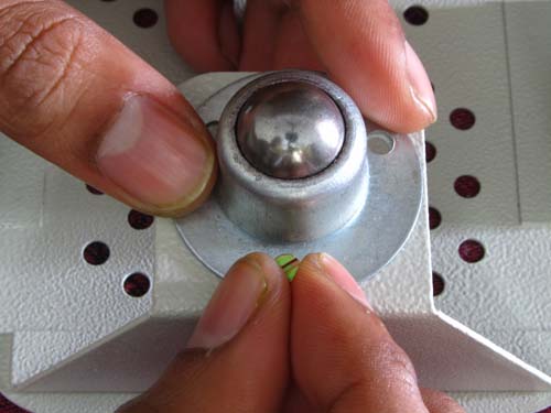 |
Installing the front castor |
 |
Mounting hole for wheels screw |
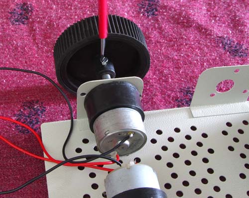 |
Mounting the wheels |
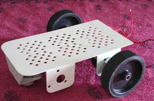 |
Chassis is ready! |
The Electronics
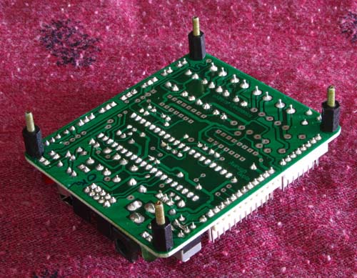
The robot is controlled using xBoard v2.0 which has ATmega32 as main CPU and integrated motor drivers. We have connected xBoard v2.0 with PC using a CP2102 USB to UART module.
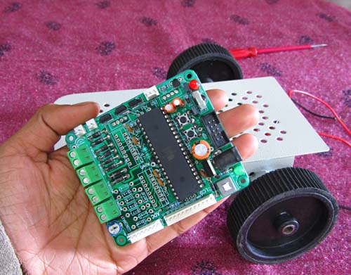 |
xBoard v2.0 |
 |
Mounting Screws |
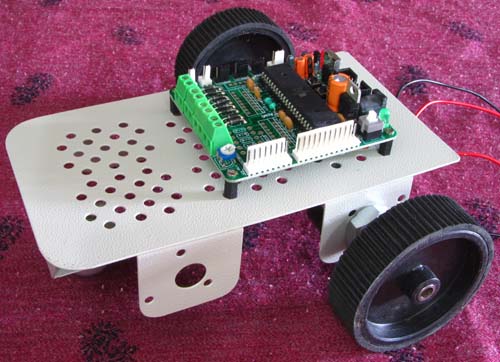 |
xBoard v2.0 mounted on chassis |
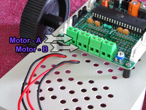 |
Motor connectors |
Connect right motor to MOTOR-A Connector and left motor to MOTOR-B.
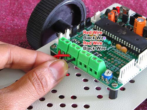 |
Motors connected |
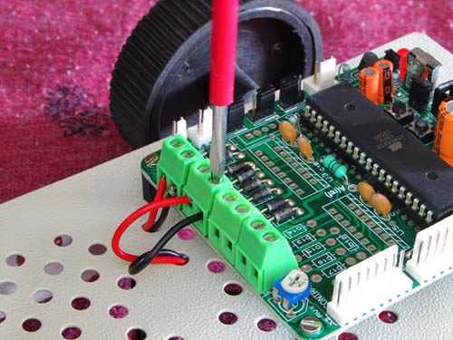 |
Fasten the screws |
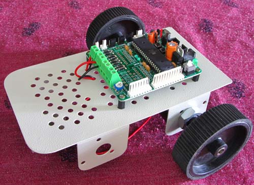 |
Neat ! Isn’t it ? |
Download and Burn the Firmware HEX file
Download the firmware hex file from the link given below and program it to the xBoard v2.0 using a USB AVR Programmer. Make sure the fuse bits are set as follows :-
HIGH Fuse = 0xC9
LOW Fuse =0xFF
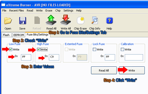 |
Fig.: Setting the Fuse bytes. |
CP2102 Module Connection
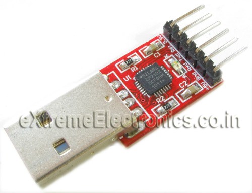 |
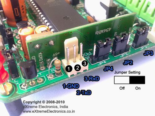
CP2102 Module (USB to TTL) |
 |
Neat ! Isn’t it ? |
Connect one side of CP2102 module to USB and other side to xBoard v2.0 as listed below.
| xBoard v2.0 | CP2102 Module |
| RxD | TxD |
| TxD | RxD |
| GND | Gnd |
other pins of CP2102 are unused.
Notes:
- Make sure that CP2102 drivers are installed.
- Jumper JP4 is in Off position (non white side)
- Jumper JP2 and JP3 are in On position (white side)
Finding the COM port number of CP2102 module.
A PC can have several COM ports, each may have some peripheral connected to it like a Modem. Serial Ports on PC are numbered like COM1, COM2 … COMn etc. You first need to figure out in which COM port you have connected the AVR. Only after you have a correct COM port number you can communicate with the AVR using tools such as Hyperterminal. The steps below shows how to get COM port number in case of Virtual COM Ports.
Right Click on "My Computer" icon in Windows Desktop.
My Computer Icon on Windows Desktop |
Select "Properties"
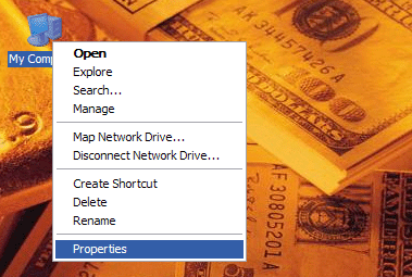 |
System Context Menu |
The System Properties will open up. Go to the "Hardware" Tab.
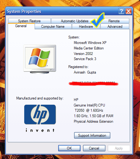 |
System Properties. |
In Hardware tab select "Device Manager" button. It will open up device manager.
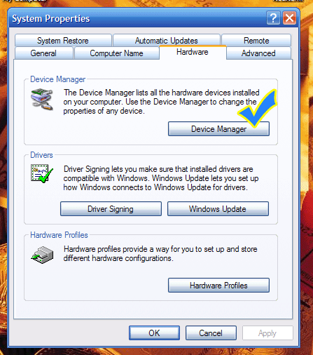 |
Open Device Manager |
In Device Manager Find the Node "Ports (COM & LPT)"
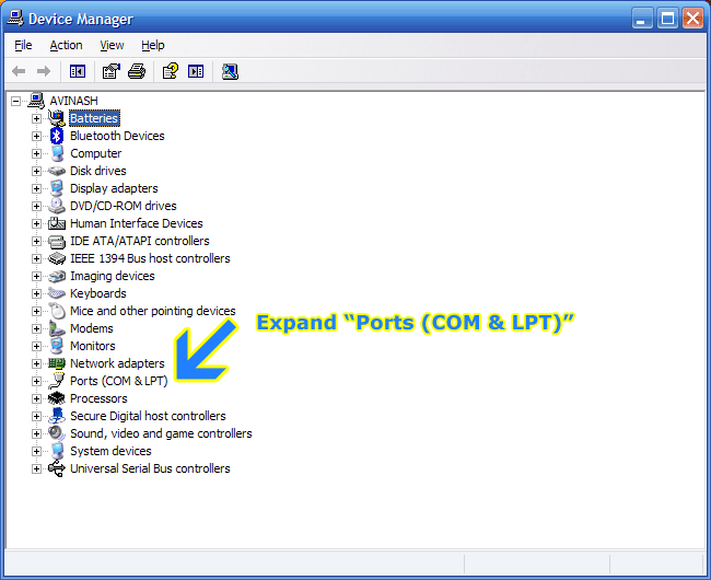 |
Expand the PORT node in Device Manager |
Depending on whether you are using a "USB to Serial Converter" or "CP2102 USB/USART Bridge Module" you have to find the port with following name.
- Prolific USB-to-Serial if you are using Bafo USB to Serial Converter.
- Silicon Labs CP210x if you are using CP2102 chip.
Note down the COM port number next to the port name. You need to open this Port in Hyperterminal.
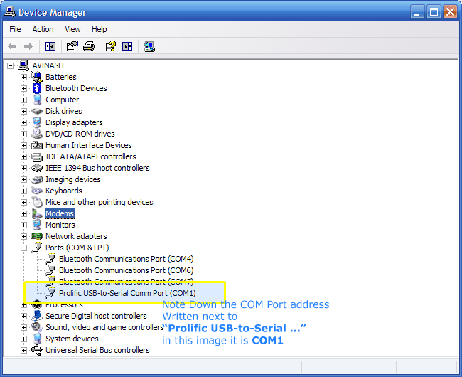 |
COM Port Number |
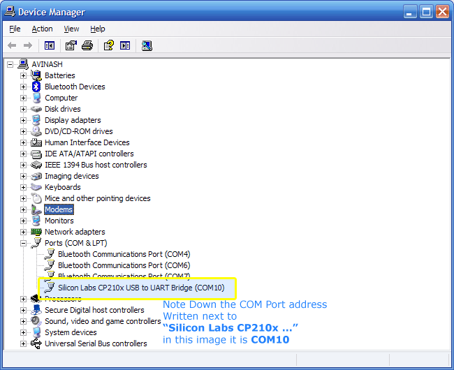 |
COM Port Number |
Setting Up Real Term
If you are running Windows Vista or Windows 7 then the Hyperterminal Program may not be available. So in place of it you can use Realterm. It can be downloaded from here.
Start Realterm from its Desktop Icon. You will get a screen similar to this.
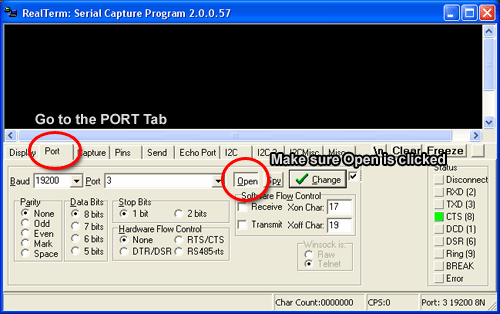 |
Real term setup |
Go to the "Port" tab and make settings as shown above. Port number is the COM Port number of CP2102 you have found above.
Note:
- Baud is set to 19200
- "Open" button is in depressed state.
Now turn on the xBoard v2.0, you will see the following message pops on the terminal.
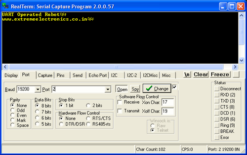 |
Greeting message from robot |
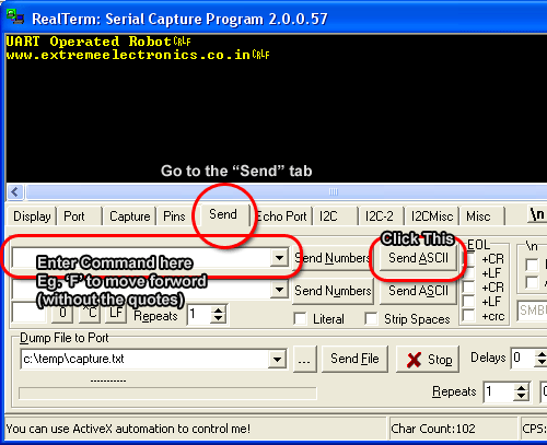
Sending command to your robot.
 |
Sending commands |
- Go to the "Send" tab
- Enter the command Eg. ‘F’ without the quotes.
- Click "Send ASCII" button.
If every thing goes well the robot will respond with message "Forward" (or any other command you gave like "Turn Right") which will be shown on the terminal screen.
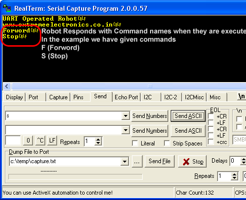 |
Sending commands |
In the same time the robot will start moving forward.
Source Code (Members Only)
[download#1]Facing problem with your embedded, electronics or robotics project? We are here to help!
Post a help request.


Hello sir
The concept is amazing. But the connection between the car and PC is still wired. Please change the CP2102 Module (USB to TTL) and use a RF module with serial port. Then the robot can move more than this.
Sir..
I need to know that whether i can control the robot with PC(wireless).
Answer to all “can”s are “yes”
Sir ..i am making the same thing but in wireless mode…So can u suggest the floating ground connection for it
well you ALBIN and SKB you just need to do the following
connect the tx pin of Microcontroller to the RX of wireless transmitter module and connect the Tx wire of reciever module to Rx of the serial com port in pc or laptop.
thats it. you can find lots of wireless transmitters, recievers and transcievers online
Mr.Sudarshan…thank u very much for sending this useful suggestion..i will try out the same…n if i face any problem i will make a mention of it..thank u sir
if want to control Rob via wireless communication then i suggest you to use bluetooth serial module for clear data transmission, connect it to rob and then you can control rob with your laptop built in bluetooth.
I want to make this with AT89S52…will it be compatible to work with the above suggestion by Mr.Avinash ??
@Skb
Sorry I was born after 1987 so don’t know about AT89S52. Is it some kind of chocolate cake ?
@Avinash…ha ha…its Atmel’s 8051 MCU…any changes i need to make?
Hi skb,
Please keep this request to jokes only.
I think you don’t deserve the answer to this question.
Sorry, but this place is not for ARTs students.
hi sir
this is pravallika
iam also doing the same project but it is controlled by wireless using rf communication
So, how can I help? See this for more info on RF Comm
https://extremeelectronics.co.in/rf/rf-communication-between-microcontrollers-part-i/
Hope it helps.
Hi,
I suggest to everyone who wants a wireless link should go for Bluetooth module(AUBTM 20)…
I am recently working on it, it’s easy to configure and the error ratio is ‘eXtreme’ly less ?
i m using bluetooth module hc-05(configured as both master and slave) i buy it at 7$ and i m controlling my rob from my laptop
i am making pc controlled wireless robot using atmega128 and bluetooth device as wireless device.
can u provide me the code for this project.
@Rohan,
You are making the robot and I provide the code ??? Why ???
sir , i am having serious problems with communications in usart , i wanted to ask is it necessary to use an external crystal oscillator for usart or we can do serial communication without external oscillator
@Pushkar
It not necessary to use external crystal.And refer the data sheet to know the error in internal oscillator frequency you using.
full project all parts cost, email me
Hi Avinash,
For the 12V DC motors (the one I have are rated 12V, 300mA), I’m experimenting with battery power. Looks like standard 9V or AA batteries are no good. What kind of batteries you recommend to run the motors. (I have four motors as I’m not using a castor wheel or a dummy motor)
Hi
U have directly given the .hex file to burn into microcontroller
can u please post the entire programe like u have posted for other tutorials (basic microcontroller and obstrucle detector)
@Srinath,
We are slowly making this site members only. So only privileged member gets the code. Their are several reasons to it. Since you are NOT a member we cannot give code to you.
How can I become a privilaged member?
registering into your website or should I have to pay some money?
Hi
I have an account in your website and I have bought a development board and USB to UART Bridge – CP2102 also recently. Still I cant see the programe for PC-controlled robot. How can I download that?
@Srinath,
Your order ID please!
Sorry but its NOT something that could be purchased by money.
We see the over all behavior of a person, how he/she helps others.
How he/she helps the company grow.
We have not much data about you in our community.
If you have a blog or website that helps spread knowledge then you may be approved instantly!
If you don’t have (that means a zero contribution to our community) then you may have to wait in queue.
Bye
my ID in your website is my gmail id only that is
user name : “naath.sri@gmail.com”
@Srinath,
Sorry you do NOT qualify for the membership.
thats what I am asking sir
How can I become a member?
k fine thank you
I dont have serial port in my laptop.
USB to UART Bridge – TTL Signals – CP2102 Based (M2)
or
USB to Serial Adaptor
so which 1 is better?
@Sagar,
Both are same just different type of USB Connectors and angle of breakout pins.
ok
and thnx.
I want to buy 10 12V dc 10 rpm geared motors.
hi avinash…..here are my works
http://www.youtube.com/user/sairamrockzzz/videos
could i get a membership here….im a arduino based developer..just wanna get dipped in avr!!
i want to be a member
please send me the installation program for controller for pc control robot
how to programming PC Controlled Robot?
pliz provide me the link for downloading the source code
can we run a robot using arrow keys in keyboard…
I AM RUNNING A PC CONTROL ROBOT USING letters and no.s.. but how to run a robot using arrow keys in keyboard.. i am using UART in atmega8..
i need the source code…help
please i need the source code
How should i become a member???
Sir, I am a student studying in class 7. Please tell me how to make a car controlled by a wireless keyboard by python progrommaning language. Please tell information on my email is kathareaniket@gmail.com
hi sir
i’m a student and beginner in this field
i try to learn work with microproseccor like AVR chip and i like do some project
one of this exact same with your project and when search about Open Source Project
i observed this.
this is very cute and i want ask from you how i can do some thing like this?
thanks a lot.
Sir I Followed the tutorial and got succeed in first attempt, then i watched your RF tutorial (mine RF module is little different from yours) 433MHz. I did the connections from one MCU board to another. But it simply doesnt work, It is continuously receiving garbage. I am facing this problems for 2 weeks and cant find help on web, PLEASE HELP
sir, how i will be member of your website?plz tell me, i acutely wish to be member.