Hello All!,
Accelerometer applications are hot these days. So today I will show you how you can easily make a accelerometer add on for your AVR GLCD Board. Once you make this you can plug it into the AVR GLCD Board any time you wish to run a accelerometer based application on it. I will also provide a simple Open Source App for the AVR GLCD Board that can be used to test the accelerometer in no time. Developers can use this demo as a base for any accelerometer based app.
Things you will need are
- A Veroboard or general purpose prototyping PCB (dotted one, not the line one).
- Female Burg Strips
- Female Burg Strip R/A
- MMA7260 Accelerometer Board
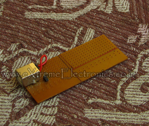 |
Fig.: A Veroboard Marked for Cutting |
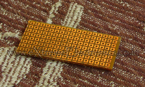 |
Fig.: Veroboard Cut to Size |
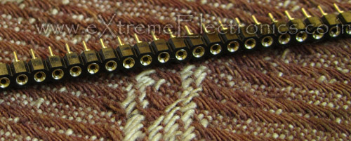 |
Fig.: Burg Strip Female |
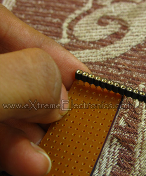 |
Fig.: Burg Strip Female Soldered to Veroboard. |
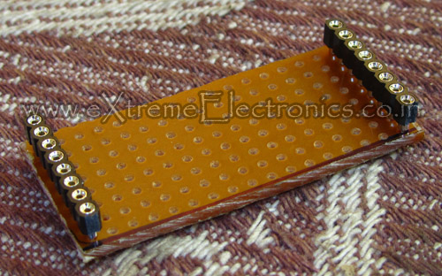 |
Fig.: Burg Strip Female Soldered to Veroboard. |
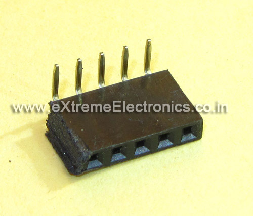 |
Fig.: 5 PIN Burg Strip Female Right Angle |
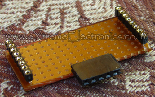 |
Fig.: R/A Burg Strip Soldered. |
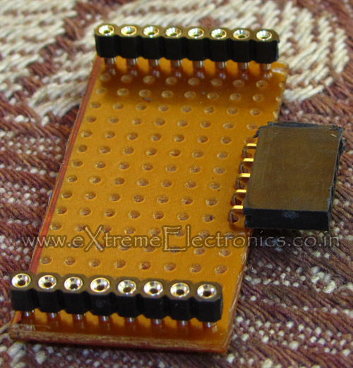 |
Fig.: Just Ready! |
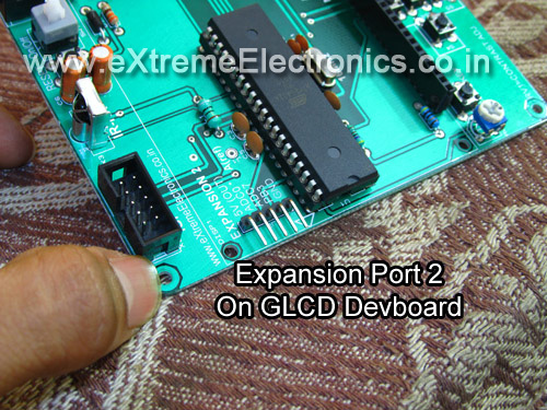 |
Fig.: AVR GLD Dev Board |
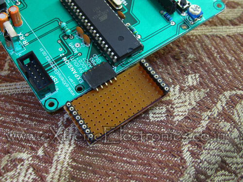 |
Fig.: Accelerometer Expansion Board Connected |
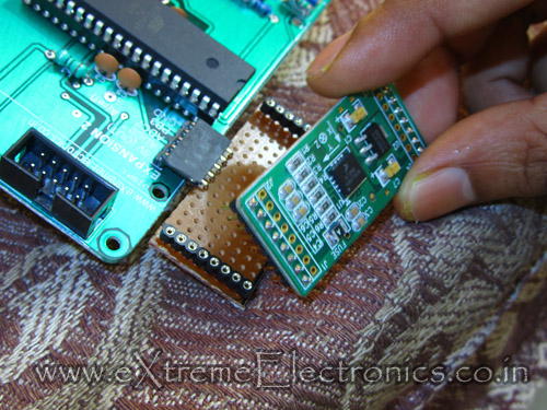 |
Fig.: Accelerometer Connected. |
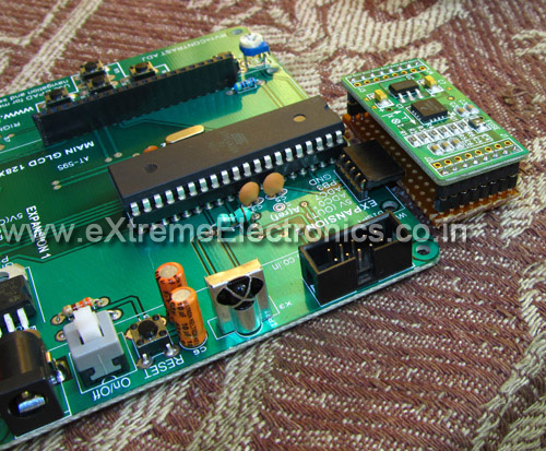 |
Fig.: Accelerometer Connected with AVR GLCD Board |
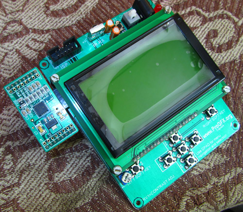 |
Fig.: AVR Accelerometer Ready! |
Connections
| CONNECT TO | ||
| GND | Ground Supply | Ground (EXP Port) |
| VDD | 3.3 V OUT | SLEEP |
| Sel2 | G Select Pin2 (See datasheet) | N/C |
| Sel1 | G Select Pin1 (See datasheet) | N/C |
| X | X axis output (g bias point @ 1.65v) | ADC0 (EXP Port) |
| Y | Y axis output (g bias point @ 1.65v) | ADC7 (EXP Port) |
| Z | Z axis output (g bias point @ 1.65v) | N/C |
| Sleep (Active Low) | Low= Sleep High* = Wake | VDD 3.3 V OUT |
| GND | Ground Supply | Ground (EXP Port) |
| +5v | 5 Volts IN | 5v (OUT) (EXP Port) |
| DO | NOT USED | N/C |
| DI | NOT USED | N/C |
| CLK | NOT USED | N/C |
| EN | NOT USED | N/C |
| RXD | NOT USED | N/C |
| TXD | NOT USED | N/C |
- N/C = Not Connected.
- EXP Port = Expansion Port 2 on AVR GLCD Dev Board
About the Demo Code
The demo code needs ProGFX.org graphic drivers to be linked with final hex code in order to run. So please make the AVR Studio/WinAVR project exactly as described in this tutorial.
About the hardware
You need to make the base hardware that is compatible with ProGFX.org graphic driver. The detailed step is given here.
The hardware can be used to run a variety of apps written using ProGFX api. A 100% ProGFX compatible board is our AVR GLCD Development Board which will be available for sale in a week or two from our online store.
Videos
Downloads
Facing problem with your embedded, electronics or robotics project? We are here to help!
Post a help request.


Hallo,
the download option don’t work on this webside.
Where can i get this demo.
Best recards D.Schnabel
sir, i always like your tutorials.I want to thank you for all your tutorials.Also it is my dreams to be a man like you.
Thank you………..
@Arnab,
Thank you.
I am developing on a similar kind of project now , in this you have used an analogue acceleration sensor but i am using a digital accelerometer (MMA7660)
which follows I2C protocol and its output is a synchronous , so there is now way to make the accelerometer wireless as much as i know is there any way to make this sensor wireless…..if you know please give me some idea …..
thanking you,