Hello Friends!,
RFID is a great technology, has may uses and become very cheap and easy to implement these days. Very interesting and useful project can be made by using RFID technology. In our tutorial series on RFID we will get introduced to this magical technology and practically create RFID based solutions.
In RFID or Radio Frequency Identification their is a tag (or label) which has a unique ID stored on it. We can read this ID by using a RFID reader. Not much fun yet? Well the features which makes magical are :-
- The RFID tag does not need to make any electrical contact with reader (Wow!)
- The RFID Tag is an active device which has a chip and antenna but does NOT need any power and are low cost!(Some tags need battery)
- RFID tags are very small, don’t need battery so can be put in cards (looks like a credit/ATM cards) or key chains.
By reading the features offered by RDIF technologies you may be wondering that the application would be much sophisticated or costly. But the good news is that we have done enough research to find the best RFID solution and they are available from our online shop. And with the help of our beginner friendly tutorials you can easily get it to work in no time.
RFID Example
For example RFID may be used to identify a person in a secure access system as shown below.
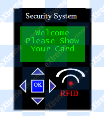 |
RFID Security System |
As soon as a RFID Tag (Which may be a card or a key chain) is brought near the system, it recognize the person and grant access.
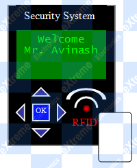 |
RFID Security System |
The great thing is that you don’t have to open your wallet and bring out the card (as you do for credit or ATM cards), just bring out the wallet and bring it near the system that’s it!
The images below shows some example of RFID Tags. Note that the pen and the Credit Card are not tags they are just for scale.
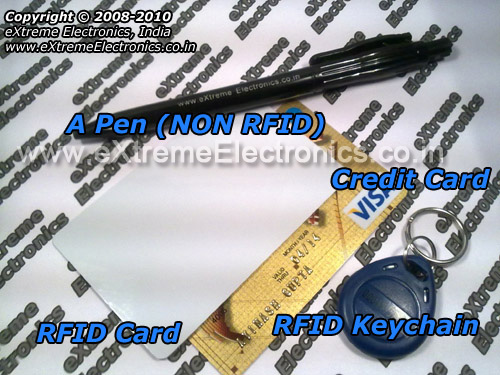 |
RFID Tags |
UART Based Plug and Play RFID Reader.
In order to read any RFID tag you need a RFID Reader. We have a great UART based Card Reader Module at very low cost. It is a complete module with Antenna and Logic Chip (which handles everything). The module does everything and sends the final decoded card number (in HEX format) via UART. As you may know UART is a hardware which sends and receive data in a protocol called RS-232. RS232 is the simplest serial protocol. It is so common that nearly all MCU supports RS232 via one or more USARTs(also called UART). We have a nice collection of beginner friendly tutorials on RS232 and USART on both Atmel AVRs and PIC MCUs.
NOTE: You can buy the module and tags from this link.
UART Communication involves just 2 data lines. One of them is called RxD (Receiving Data) and Another is called TxD (Transmitting Data). One more line called "common" is also necessary between two isolated systems. Normally GND is kept common between all devices and modules. Since RFID Reader Module only sends data and does not receive any data, only Tx line from RFID is used.
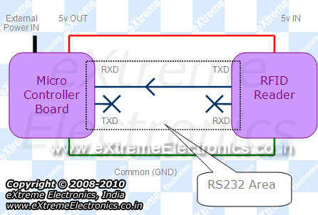 |
Typical Interface between MCU and RFID Reader |
In the above diagram please note the following facts.
- Microcontroller board is powered from an external source like DC adapter or battery.
- Microcontroller board has 5v regulator built in.
- 5v Output is available from above regulator.
- The 5v out is feed to the RFID reader which powers the module.
- Tx line from RFID reader is feed to the Rx line of MCU.
- Tx line of MCU and Rx line of RFID Reader are unused.
More information on USART and RS-232
- RS232 Communication – The Basics
- Using the USART of AVR Microcontrollers.
- Using the USART of AVR Microcontrollers : Reading and Writing Data
Now when a Card (tag) is brought near the RFID reader, it tries to communicate with the tag, receives the data and decodes it. Finally it send the data over the Tx line. The UART module in MCU receives the data and USART library buffers it into the internal memory. The user program running on the MCU wait till the USART library informs it that sufficient data is available (in this case more than 13 bytes). When data is available, user program can read and validate the data. After that it can be used as per application requirement. For example if card number matches internally stored card number, the user is granted access to the system or open a door and log the entry time of that person in a database.
Too much theory? Now lets get physical!
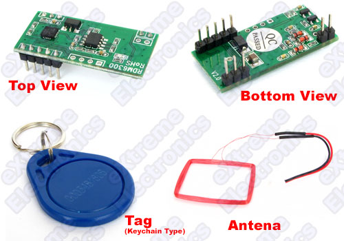
How an RFID Reader Module Looks ?
See it your self.
Serial RFID Reader |
NOTE: You can buy the module and tags from this link.
PIN Configuration of RFID Reader
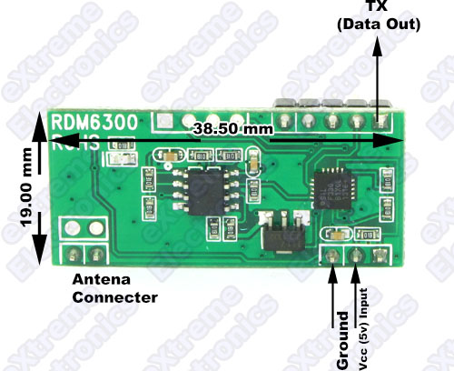 |
PIN Configuration |
The antenna that comes bundled with the module can be easily connected by just plugging it in.
RFID Reader Test Circuit.
In this tutorial we will create most basic circuit for testing RFID Reader. Once you complete this successfully, you know how to get data from RFID Reader. You will also have working code that you may use with other more useful projects.
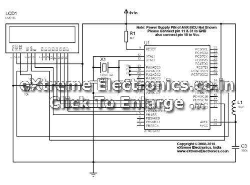
The test circuit will be built around ATmega32 microcontroller. The output device will be a 16×2 lcd module. So we set up a basic ATmega32 circuit. The circuit will have the following :-
- ATmega32 MCU
- 16MHz Crystal
- Reset Circuit.
- 5v Power Supply Circuit.
- ISP (For programming)
- LCD Module.
- LCD Module Contrast adjust pot.
Schematic for AVR ATmega32 and LCD Connection. |
Please note that power supply circuit is NOT shown in the above schematic. You will need a 7805 voltage regulator IC in order to generate 5v from any source of 8-18v.
The above circuit is so common that you may require it as a base for several projects and experiment. For that reason we have made a fully assembled and tested unit on a professional PCB. You can buy one of them from the following link.
- xBoard v2.0 – Advance AVR Development Board.
- USB AVR Programmer v2.0 (Needed for Burning Programs to AVR MCU)
If you are using the xBoard v2.0 then you don’t need to built any circuit. Just hookup the LCD Module as shown below.
 |
12 PIN Header For LCD Module Connection on xBoard. |
 |
LCD Module Connected. |
 |
The Whole Setup. |
Other wise you may also buy a Low Cost AVR Development Board, but it does not has inbuilt LCD Module connector so you need to solder it your self at the free area (and also do the wiring).
Extra 5v out is available in most development board. Connect the 5v from the dev board to the RFID Reader. And the TX pin from the RFID Reader to the dev board’s RX pin.
- On Low Cost AVR Development Board it is labeled Rx.
- On xBoard v2.0 is on the 3 pin relimate connector. See USART Section in this documentation.
- On your own board it is on PIN 14 of ATmega32. Also labeled PD0 as it is muxed with PORTD.
At the software side we will be using LCD Driver to control the LCD Module and the USART library for receiving data from the RFID reader. More information is available from the following links.
- Using LCD Modules with AVR Microcontrollers.
- Buffered USART Library for AVRs (see source code)
It is highly recommended to go through the above links in order to get what each function is doing.
RFID Reader Test Program for avr-gcc
/**************************************************************

Simple program to demonstrate the use of USART based Plug
and Play RFID reader. The program uses the following components.

* LCD Library : For Controlling a Standard 162 LCD Module
* USART Library : For Receiving Data from RFID Reader.

Program sets up USART @ 9600bps with following configuration.

*8 bit frame
*1 stop bit
*NO Parity

The UBRR Value Required is 103 (See page 168 on datasheet)

Program waits until more than 13 bytes are received over USART.

When 13 or more bytes are received we may have got one or
more RFID data packet. The program checks if the first data
byte is 2 or not. If it is 2 then it indicates that a valid
data packet is recived. The program then dumps the next 11
bytes to LCD Screen. These are the card data bytes. It then
ignores the last byte.

More information on every subject including

*Basic AVR MCU tutorials.
*USART and RS-232 Tutorial.
*LCD Interfacing Tutorial

and many other information is available on site

http://www.eXtremeElectronics.co.in

                            NOTICE
                           --------
NO PART OF THIS WORK CAN BE COPIED, DISTRIBUTED OR PUBLISHED WITHOUT A
WRITTEN PERMISSION FROM EXTREME ELECTRONICS INDIA. THE LIBRARY, NOR ANY PART
OF IT CAN BE USED IN COMMERCIAL APPLICATIONS. IT IS INTENDED TO BE USED FOR
HOBBY, LEARNING AND EDUCATIONAL PURPOSE ONLY. IF YOU WANT TO USE THEM IN
COMMERCIAL APPLICATION PLEASE WRITE TO THE AUTHOR.


WRITTEN BY:
AVINASH GUPTA
Mail: me@avinashgupta.com
Bio:  www.avinashgupta.com


**************************************************************/
#include <avr/io.h>

#include "lcd.h"
#include "usart.h"

/* Simple Wait Function */
void Wait(uint8_t t)
{
   uint8_t i;

   for(i=0;i<t;i++)
      _delay_loop_2(0);
}

void main()
{
   Wait(50);

   //Init LCD Module with NO Cursor
   LCDInit(LS_NONE);

   //Init USART @ 9600bps
   USARTInit(103);   //UBRR Value = 103 for 9600bps
               //(See page 168 on Datasheet)

   LCDClear();

   LCDWriteString("RDIF Test #1");

   Wait(50);

   while(1)
   {

      LCDWriteStringXY(0,0,"Show Your Card");   //Message on line 1
      LCDWriteStringXY(0,1,"Waiting    ");   //Message on line 2

      //Check if USART has Got data from RFID
      //RFID packet is always 13 bytes long
      if(UDataAvailable() >= 13)
      {

         //Check the First byte it must be 2
         if(UReadData() == 2)
         {
            //We got correct packet!
            //Display it on LCD
            LCDClear();
            LCDWriteString("Card Data >>");

            //Go to start of 2nd line on LCD
            LCDGotoXY(0,1);

            //Dump Remaining 11 bytes
            uint8_t i;
            for(i=0;i<11;i++)
            {
               LCDData(UReadData());
            }

            //Read and discard the last byte (Stop Byte)
            UReadData();

            //Wait so that user can read the LCD
            Wait(200);

            //Now Clear it
            LCDClear();
         }
      }


   }
}
Compile the above program using AVR Studio (compiler is avr-gcc). And finally burn the program using any ISP Programmer to the ATmega32. The fuse bits must be set as following to enable external crystal as clock source.
- High Fuse = C9 (hex value)
- Low fuse =FF (hex value)
Finally turn on the power and bring a RFID Tag near the antenna of RFID Reader. The card number (in hex number system) will be displayed on the screen.
Troubleshooting
- NO Display on LCD
- Make sure AVR Studio Project is set up for clock frequency of 16MHz (16000000Hz)
- Adjust the Contrast Adj Pot.
- RFID Reader is NOT reading card.
- Make sure you have bought compatible 125KHz tags.
- Use only 16MHz crystal (for other value you need to change the program)
- Fuse bits are set as told above.
- Compiler Errors
- Many people these days has jumped to embedded programming without a solid concept of computer science and programming. They don’t know the basics of compiler and have very less experience. To learn basic of compilers and their working PC/MAC/Linux( I mean a desktop or laptop) are great platform. But embedded system is not good for learning about compilers and programming basics. It is for those who already have these skills and just want to apply it.
- Make sure all files belonging to the LCD Library are added to the "Project".
- Make sure all files belonging to the USART Library are added to the "Project".
- avr-gcc is installed. (The Windows Binary Distribution is called WinAVR)
- The AVR Studio project Type is AVR GCC.
- Basics of Installing and using AVR Studio with avr-gcc is described in this tutorial
- How to add files to project is described in this tutorial.
- General Tips for newbies
- Use ready made development boards and programmers.
- Try to follow the AVR Tutorial Series from the very beginning. (Remember the list spans four pages, page 1 is most recent addition thus most advance)
Video For RFID Reader Test.
Downloads
Help Us!
We try to publish beginner friendly tutorials for latest subjects in embedded system as fast as we can. If you like these tutorials and they have helped you solve problems, please help us in return. You can donate any amount as you like securely using a Credit or Debit Card or Paypal.
We would be very thankful for your kind help.
By
Avinash Gupta
Facebook,
Follow on Twitter.
www.AvinashGupta.com
me@avinashgupta.com
Facing problem with your embedded, electronics or robotics project? We are here to help!
Post a help request.



@Av
Better than porn. Great stuff Av. Thanks again!
Hi….
thats good..
thanksss
SIR
I am in a requirement of RFID enabled device for writing data on tag… I am having a device for reading data manufactured by you.. Do you have RFID writer along with reader…and could you provide me the code for writing along with the libraries…
@Piyush
We do not have RFID Writer right now.
Pingback: Getting Started with Serial RFID Reader | eXtreme Electronics
hello…i want to buy this RFID reader…I am from Bangladesh…can u tell me how much it cost?(including the shipping) and how can I pay?
Thank you very much Avinash Sir. Hats off to your great hard work!! you have a great talent of explaining things in easy way. Thanks again
Hello sir,
I am an engineering student from Pune,India and making a project related to Active RFID.So in that case I need an active RFID reader.So please tell me total cost of the reader along with any shipping charges,if applicable.
My mail-id is: kshitijshah9@gmail.com
Thank you.
Sir,
we r in the need of RFID reader for our final year project. we need a reader to read the rfid tag and to transfer the information to the computer. we want to know the price of the reader for this purpose.. we dont know how to interface reader wit the system…. is there any software for this purpose? pls help us…
hello priya ,
i also want an interface between pc and rfid reader did you get any software or any other thing that will work .
actully my idea is that rfid reader ll read the card detect the name or data stored in it and ll display the information stored in pc related to that rfid card holder . so if u can help me pls do 🙂
thankyou
Sorry this post is late but you can write a log file in CSV which is compatible with Microsoft excel to display your data.Your data can be sent to a PC using any of the serial lines; RS232 or parallel medium.Make sure to use a usb-to- serial converter should your PC not have a DB9 header. Best of luck!
hello avinash!!
your website is too good. We are using rfid and gsm modules for our project, the problem is both need serial communicatoin.. i found out that rfid can be interfaced using wiegand communication. can you pls help me out in that.. Wiegand commn required for rfid interfacing.. thanks in advance!!
hello avinash,
can i get your help regarding the wiegand communication for rfid interfacing using data pins.. please help me
Sir,
we r in the need of RFID reader for our final year project. we need a reader to read the rfid tag and to transfer the information to the computer. we want to know the price of the reader for this purpose.. we dont know how to interface reader wit the system…. is there any software for this purpose? pls help us
Dear Sir,
I have bought this RFID reader and tags from eXtremeelectronics.com. I am trying to interface it with PIC 16F870.
I am trying to write an interrupt driven serial communication program which reads byte by byte sent by RFID reader and then display byte by byte on single 7 segment display, each byte lasts for 3 secs. on display.
Now I have lot of confusions in my mind regarding this reader like what should be baud rate, XON/XOFF status, how many bytes I will receive (so I can set array size), whether I will get RFID packets continuously until tag is in front of antenna or reader send that 13 or 14 byte packet at once only?
Can you please tell me how to write the program for this microcontroller or at least send the flow chart of working of this RFID reader. I haven’t get any data sheet or manual with this which is surprising…!
Thanks.
Hello Avinash,
Thanks for this great tutorial, I am not getting the card details on LCD, but when I removed the loop to check if first byte is 2, I got the display of the number printed on card(not HEX value) along dollar symbol in the first and two junk values at the last.
Kindly help me out with this.
@Avi Kindly Move the discussion to forum
http://forum.extremeelectronics.co.in/
sir , im using a passive rfid concept for my project .I want to interface two rfid reader with a single atmega16 board.but , the problem is i hav only one RXD(receiving) pin in the board . what do i do ,for TXD pin of second reader ??
Manjunath k s,
Its very simple, you have to understand how data are sent over serial protocol and use on input pin to receive the data. In short it is called software USART because it mimics the function of actual hardware USART peripheral of MCU.
hi, i have two more doubts regarding above topic.
a) when i actually read the data from tag to the reader , what kind of data is sent to the lcd via atmega16 . does it diplay the id no whatever written on the tag or something in different formats(like HEX ) .IF i get the data on lcd in lcd , what should i do to get the id itself??
b) you have used some strings like UDataAvailable() and UReadDATA().
but these two are not declared in the main ? is it correct ??
Can you plz tell me whats wrong in my code to read the tag from rfid reader. im getting varieties of symbols and characters on my lcd output
#include
#include
#include “lcd_lib.h”
void usart_init(uint16_t ubrr_value)
{
UBRRL = ubrr_value;
UBRRH = (ubrr_value>>8);
UCSRC=(1<<URSEL)|(1<<UCSZ0)|(1<<UCSZ1);
UCSRB=(1<<RXEN);
}
unsigned char usart_getch()
{
while ((UCSRA & (1<< RXC))==0);
return UDR;
}
void getcard_id(void)
{
int i;
unsigned char card[12];
for(i=0;i<12;i++)
{
card[i] = usart_getch();
}
return;
}
void LCD_DISPLAY(void)
{
int i;
unsigned char card[12];
for(i=0; i>”);
_delay_ms(10);
while(1)
{
getcard_id();
LCDGotoXY(0,1);
LCD_DISPLAY();
}
return 0;
}
Hi Avinash,
Thanks for this great tutorial, which i found very helpful in understanding the underlying concept of RFID, is it possible to get the rfid data from the reader on RJ45 port which may help in extending the distance between the reader and the computer
Hi avinash
I am working on this project but card data is not printed on lcd can you plz help sir as soon as possible
@AMRIT KANT PANDEY
Please buy fully assembled set at Rs. 2500/-
Hi avinash,
Can u email me usart.h file at rutupatel93@yahoo.com?
I am trying to check this code in atmel studio 6.
i am doing project regarding RFID scanner that requires SPI interfacing with atmega32 so can you please share the SPI code also or just some basics regarding that
can you help me ?? how this sorce code if using CV AVR compiler/progamer ?? thank’s send on my email : anandananda331@gmail.com