Detecting colour of an object can be an interesting and useful electronic application. It can be realized using a colour sensor like TCS3200 and a general purpose microcontroller like AVR ATmega32.
TCS3200 Colour Light to Frequency Converter Chip
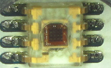 |
Fig. TCS3200 Chip . |
TCS3200 chip is designed to detect the colour of light incident on it. It has an array of photodiode (a matrix of 8×8, so a total 64 sensors). These photodiodes are covered with three type of filters. Sixteen sensor have RED filter over them thus can measure only the component of red in the incident light. Like wise other sixteen have GREEN filter and sixteen have BLUE filter. As you should know that any visible colour can be broken into three primary colours. So these three type of filtered sensors helps measure the weightage of each of primary colours in incident light. The rest 16 sensors have clear filter.
TCS3200 converts the intensity of incident radiation into frequency. The output waveform is a 50% duty cycle square wave. You can use the timer of a MCU to measure period of pulse and thus get the frequency.
The output of TCS3200 is available in single line. So you would ask how we get the intensity of RED,GREEN, BLUE and CLEAR channels? Well it has two inputs S2 and S3 that is used to select the sensor whose output need to be made available on the out line.
S2 |
S3 |
|
| RED | L |
L |
| GREEN | H |
H |
| BLUE | L |
H |
| CLEAR | H |
L |
So we select a channel either RED, GREEN, BLUE or CLEAR and then do the measurement of the output pulse width to get that channel’s intensity. In our library we have made these four functions to do this task.
void TCSSelectRed()
{
   TCSS2Low();
   TCSS3Low();
}

void TCSSelectGreen()
{
   TCSS2High();
   TCSS3High();
}

void TCSSelectBlue()
{
   TCSS2Low();
   TCSS3High();
}

void TCSSelectClear()
{
   TCSS2High();
   TCSS3Low();
}
The functions TCSS2High(), TCSS2Low() etc are low level functions that controls the i/o lines connected to S2 and S3 lines.
TCS3200 Module
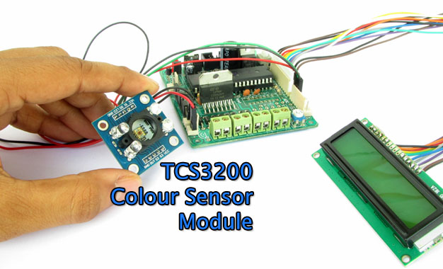
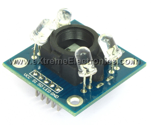
Since TCS3200 chip is a small SMD chip and is tough to prototype designs using the surface mount chip. Thus we have made a small module that has the TCS3200 chip, four white LEDs, LED control circuit and few other basic components on a PCB. The module has the connection all the line on 0.1inch male header. This makes it easy to connect with microcontroller boards. The white LEDs throws light on the object that is placed in front of the sensor. For best performance the object should be placed 1inch away from the LEDs such that the beam from all four LEDs converge at a single point (and do not make four distinct light spots on the object). One i/o pin of MCU can be used to switch on and off the LED.
In our library we have made two functions to control the TCS3200 module’s LEDs.
TCSLEDOn()
TCSLEDOff()
Fig. TCS3200 Module. |
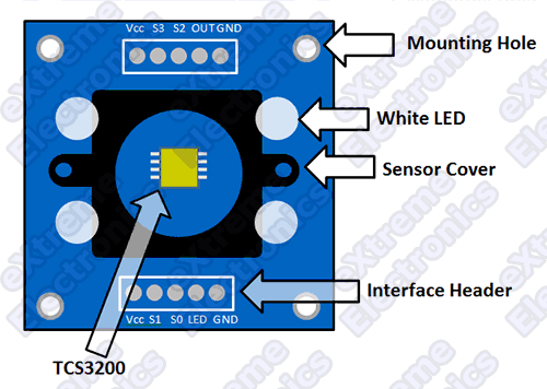 |
Fig. TCS3200 Module. |
Measuring TCS3200’s Output
For measuring the output frequency of the TCS3200 we have used TIMER1 of AVR. Which is 16 bit timer. We have clocked the TIMER1 using same frequency as the CPU that is 16MHz without any division.
The function which is used to measure the frequency of TCS3200 is named TCSMeasure() The implementation of this function is given below.
uint32_t TCSMeasure()
{
   //If the function is entered when the level on OUT line was low
   //Then wait for it to become high.
   if(!(TCS_OUT_PORT & (1<<TCS_OUT_POS)))
   {
      while(!(TCS_OUT_PORT & (1<<TCS_OUT_POS)));   //Wait for rising edge
   }


   while(TCS_OUT_PORT & (1<<TCS_OUT_POS));   //Wait for falling edge

   TCNT1=0x0000;//Reset Counter

   TCCR1B=(1<<CS10); //Prescaller = F_CPU/1 (Start Counting)

   while(!(TCS_OUT_PORT & (1<<TCS_OUT_POS)));   //Wait for rising edge

   //Stop Timer
   TCCR1B=0x00;

   return ((float)8000000UL/TCNT1);

}
Code Walkthrough
We measure the time between the falling the edge and next rising edge. So we must take care when the function is called and the level on the OUT line is already LOW (that means already some time has passed from the last falling edge, so we wait for the line to become high). As soon as a falling edge is detected we start RESET the TIMER1 counter (TCNT1 to 0). Then we start the timer by writing to the control register TCCR1B. Then we wait for a rising edge. And as soon as we get a rising edge we stop the timer and do a small calculation to calculate the frequency. Finally this frequency is returned.
Demo Program for TCS3200
A demo program which shows the use of TCS3200 function is provided below. This demo program runs on xBoard v2.0 it shows program output on a 16×2 LCD module. The program waits for an object to be placed in front of the sensor module. And when an object is placed it measures the colour of object and shows the relative weightage of RED,GREEN and BLUE components. The buzzer beeps and the LED glows whenever an object comes in front of the sensor.
  /*****************************************************************************
  Colour Sensor TCS3200 Demo Program

  HARDWARE
  --------
  MCU = ATmega32 Running at 16MHz Crystal (LFUSE=0xFF HFUSE=0xC9)

  DISPLAY = 16x2 LCD Module
  *************************

  LCD   | ATmega32
  RS  -> PD3
  R/W -> PD6
  E   -> PB4
  DB0 ->
  DB1 ->
  DB2 ->
  DB3 ->
  DB4 -> PB0
  DB5 -> PB1
  DB6 -> PB2
  DB7 -> PB3

  TCS3200 Module
  **************

        ATmega32
  S2 -> PA0
  S3 -> PA1
  OUT ->PA2
  LED ->PA3

  BUZZER -> PD7


  NOTICE
  --------
  NO PART OF THIS WORK CAN BE COPIED, DISTRIBUTED OR PUBLISHED WITHOUT A
  WRITTEN PERMISSION FROM EXTREME ELECTRONICS INDIA. THE LIBRARY, NOR ANY PART
  OF IT CAN BE USED IN COMMERCIAL APPLICATIONS. IT IS INTENDED TO BE USED FOR
  HOBBY, LEARNING AND EDUCATIONAL PURPOSE ONLY. IF YOU WANT TO USE THEM IN
  COMMERCIAL APPLICATION PLEASE WRITE TO THE AUTHOR.


  WRITTEN BY:
  AVINASH GUPTA
  gmail@avinashgupta.com (Yes ! It's correct !)
*******************************************************************************/

#include <avr/io.h>
#include <util/delay.h>

#include "lib/lcd/lcd.h"
#include "lib/colour_sensor/tcs3200.h"

uint32_t MeasureR();
uint32_t MeasureG();
uint32_t MeasureB();
uint32_t MeasureC();

int main(void)
{
   //Initialize the LCD Library
    LCDInit(LS_NONE);

   //Clear LCD
   LCDClear();

   //Initialize TCS Library
   InitTCS3200();

   //Buzzer Pin as output
   DDRD|=(1<<PD7);


   uint8_t x=0;
   int8_t vx=1;

   while(1)
   {
      LCDWriteStringXY(0,0,"    Waiting.    ");

      TCSLEDOn();
      uint32_t v1=MeasureC();

      _delay_ms(100);

      TCSLEDOff();
      uint32_t v2=MeasureC();

      uint32_t d=v1-v2;

      if(d>8000)
      {
         //Object came in range
         LCDClear();

         LCDWriteStringXY(0,0,"  Object Found  ");

         PORTD|=(1<<PD7); //Buzzer On

         _delay_ms(250);

         PORTD&=~(1<<PD7); //Buzzer Off

         //Show
         uint32_t r,g,b;

         TCSLEDOn();

         r=MeasureR();
         g=MeasureG();
         b=MeasureB();

         TCSLEDOff();

         uint32_t smallest;

         if(r<b)
         {
            if(r<g)
               smallest=r;
            else
               smallest=g;
         }
         else
         {
            if(b<g)
               smallest=b;
            else
               smallest=g;
         }

         uint32_t _r,_g,_b;
         smallest=smallest/10;

         _r=r/smallest;
         _g=g/smallest;
         _b=b/smallest;

         LCDWriteIntXY(0,1,_r,4);
         LCDWriteIntXY(5,1,_g,4);
         LCDWriteIntXY(10,1,_b,4);
         //End Show
         _delay_ms(2000);
      }

      LCDWriteStringXY(0,1,"%0%0%0%0%0%0%0%0%0%0%0%0%0%0%0%0");
      LCDWriteStringXY(x,1,"%1");
      LCDGotoXY(16,1);//Hide cursor.

      x+=vx;
      if(x==15 || x==0)
         vx=vx*-1;


      _delay_ms(50);

   }

}

uint32_t MeasureR()
{
   TCSSelectRed();
   uint32_t r;

   _delay_ms(10);
   r=TCSMeasure();

   _delay_ms(10);
   r+=TCSMeasure();

   _delay_ms(10);
   r+=TCSMeasure();

   return r/3.3;

}

uint32_t MeasureG()
{
   TCSSelectGreen();
   uint32_t r;

   _delay_ms(10);
   r=TCSMeasure();

   _delay_ms(10);
   r+=TCSMeasure();

   _delay_ms(10);
   r+=TCSMeasure();

   return r/3;

}

uint32_t MeasureB()
{
   TCSSelectBlue();
   uint32_t r;

   _delay_ms(10);
   r=TCSMeasure();

   _delay_ms(10);
   r+=TCSMeasure();

   _delay_ms(10);
   r+=TCSMeasure();

   return r/4.2;

}

uint32_t MeasureC()
{
   TCSSelectClear();
   uint32_t r;

   _delay_ms(10);
   r=TCSMeasure();

   _delay_ms(10);
   r+=TCSMeasure();

   _delay_ms(10);
   r+=TCSMeasure();

   return r/3;
}
TCS3200 Library
The TCS3200 library comes in two files
- tcs3200.c
- tcs3200.h
They must be copier to current project folder and added to Atmel Studio Project.
TCS3200 Demo Schematic
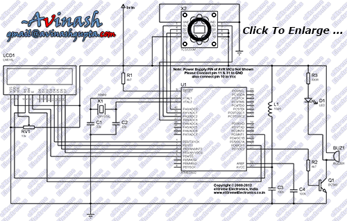
Fig. ATmega32 Interface with TCS3200 Colour Sensor. |
Related Articles
This demo makes use of our LCD Library please see the following tutorial for more information on LCD Modules and the library functions.
We have used microcontroller’s timer to measure the period of the waveform comming from TCS3200. You can consult following tutorial for basic information and usage of timers.
You can purchase the module online from our online store. We ship all over India. Payment can be made online by using debit card or netbanking account. You will receive the product within 3-5 working days delivered right to your doorsteps!
Troubleshooting
- NO Display on LCD
- Make sure AVR Studio Project is set up for clock frequency of 16MHz (16000000Hz)
- Adjust the Contrast Adj Pot.
- Press reset few times.
- Power On/Off few times.
- Connect the LCD only as shown on schematic above.
- Compiler Errors
- Many people these days has jumped to embedded programming without a solid concept of computer science and programming. They don’t know the basics of compiler and lack experience. To learn basic of compilers and their working PC/MAC/Linux( I mean a desktop or laptop) are great platform. But embedded system is not good for learning about compilers and programming basics. It is for those who already have these skills and just want to apply it.
- Make sure all files belonging to the LCD Library are "added" to the "Project".
- avr-gcc is installed. (The Windows Binary Distribution is called WinAVR)
- The AVR Studio project Type is AVR GCC.
- Basics of Installing and using AVR Studio with avr-gcc is described in this tutorial
- General Tips for newbie
- Use ready made development boards and programmers.
- Try to follow the AVR Tutorial Series from the very beginning. (Remember the list spans four pages, page 1 is most recent addition thus most advance)
Downloads
Help Us!
We try to publish beginner friendly tutorials for latest subjects in embedded system as fast as we can. If you like these tutorials and they have helped you solve problems, please help us in return. You can donate any amount as you like securely using a Credit or Debit Card or Paypal.
We would be very thankful for your kind help.
By
Avinash Gupta
Facebook,
Follow on Twitter.
www.AvinashGupta.com
gmail@avinashgupta.com
Facing problem with your embedded, electronics or robotics project? We are here to help!
Post a help request.



Hello Avinash,
First of all, thanks for this tutorial.
I’m trying to use this sensor for a job, and this tutorial helped me a lot. However I have some questions about this project, I would like to clarify.
When I turn on the lcd immediately indicates “Object found”, even not having anything in front of him, and it keeps on doing readings. Means that “d” is greater than 8000, but it should not, right?
When I put an object just get values ??ranging between 0010 and 0050, ie if I put a red object get something like 0045 0010 0010. This range is too small, right?
I hope you can help me on these questions.
Thank you
Helder
Hi,Helder
We will surely help you,we will suggest you to avoid direct exposer of sensor to sunlight or room light.Thank you
sir
we need interfacing of TCS3200 with PIC MICRO CONTROLLER 16F877A. we need it for our main project. loking for your help.
thanking you.
@Bhavana,
So how can we help? Upto what extent you can completed the project? Please clarify what help you need. Do you have the logic, flowchart, algorithms written?
I see results same you! Can you known me hardware problem of you? Thanks much!
Hello Gaurav,
I tried without direct exposure of the ambient light, and the problem continues. It will be a hardware problem?
With the module I bought, I had to turn off the pin 37 in atmega32, otherwise the program would not start. Will this be the problem?
Thanks,
Helder
Yes, it seems hardware problem.
Thank you.
Hello Avinash,
i am winnie….i’m doing my final project now…i want to ask how to do command for color sensor TCS230 which i’m using PIC16F877A with 20pin using MPLab softwear….i really2 need your help….i only have 2weeks from now to settle down the programming for color sensor….hope u can help me…
@Winnie
NO I have NO free time !
Is this IC an SM?
Is this IC an SMD?
@Abhijth
Any one with 2 (or even 1) eye can tell the IC is SMD, but don’t know why you can’t see 🙁
🙂
Dear Avinash
my name is rahul and i need a project with wireless camera. online transmitting and receiving , do you have any idea about this topic?
plz suggest me some AVR based project that you created earlier i need your help, this is my collage projet.
plz plz mail me some idea i will contact you
thanks in advance
Please tell me the optimum detection range for this color sensor. it would be of great help.
why dividing the measured values (over the delay) by factors such as 3,3.2 etc.i need to know this.kindly help me out!!
@Sherlock,
This is due to the fact that the white LEDs are NOT “PERFECT” white. So actually this technique is called WHITE BALANCING! Understood?
Since we take 3 readings, we need to divide it by 3 to get the average value ! This averaging is done to get more accurate readings. Also division by factor bigger than 3 is done to compensate for it’s higher weight in the light emitted by white LEDs.
Hello, Avinash sir… I had purchased this sensor from your store. But I dont have your xboard mini but had a development board of ATmega 8 based controller. Do these library files work for it.(except LCD file I have lcd header for it but what about TCS color sensor)
Thank You
Please Help…..
@Akshita,
What is is your Order ID?
Please do exactly as described it won’t work with other board or MCU.
Hello sir I am not able to understand the calculations done in the programme, like if(d>8000) and why there is division with 3.3, 3 and 4.2 in the MeasureR, TCSmeasureG etc. functions? can you elaborate the significance of these values and calculations.
Thaks avinash..It worked for me…but i have a doubt ..why divide the measured value by 3.3,3,4….?pls reply
sorry fro my above question.. i didnt found your answer for that..is there any problem for using 8 bit timer?
sir , how to connect a alcohal sensor with atmega16 and how to read it?
please help me….
thnx….
avinash jee…..
I got that how color is sensed.
I wana know that spare tcs3200 sensor is available or not without demux & led arrangement (i.e. module)
Even I request you to give the spare tcs3200 pin description.
Hello Avinash, great tutorial!
I wrote my code using the PIC’s capture module. It’s works.
Do you know how to validate the sensor colors values read with an object color? How do know if the measured values are correct?
Regards
Sir, how do i control a buzzer’s frequency using msp430??
@ Avinash…
would you like to share programming of library function as you mentioned these function in above tutorial….???
I cannot find the tcs3200.h for ATMEGA. Can you please tell me where to find it?
mostafanaghedim@gmail.com
I want to buy AVR Mega32 for automation of coloured yarn mesuring
befor I have purchased one color sensor TSC3200 from mashhad Iran but there was not AVR Mega 32 apinion it
would u pls help me for creating source code in Borland C2 for using sensor TSC3200 and if necessary to have AVR Mega32 detailed information to pay and buy it and so on
Best RGRDs
Mostafa Naghedi
Chaloos hachirood
IR-Iran
Hello friend, could you re-link the links to download the code in c of the project and the diagram or could you send them to my mail: matifrank7@gmail.com, greetings from Argentina. 🙂 7u7
C Source Code
TCS3200 Demo HEX file for ATmega32.
Circuit Diagram.
TCS3200 Chip’s Datasheet.
awesome