Making a programmer.
There are many different types of programmers available on the net. The basic difference is their interface with the PC. Basically, there are three types of programmers.- Serial Port based
- Parallel Port based
- USB Port based.
Of these serial port based and parallel port based programmers are easy to make in minimal cost. However, the parallel port is little bulky as compared to serial port, I prefer serial one. One of the best programmers I have come across is PonyProg(http://www.lancos.com) Serial Device Programmer it is a package of simple and low cost programmer with easy to use GUI software. I have been using it from long time. So here I will teach you to make PonyProg device programmer.
| Note |
| As the serials and parallel ports are very old technologies they are fast disappearing from PCs. Most laptops are not having them and even desktops are dropping them. Therefore, its no surprise that your PC does not has serial ports. In this case, you have to use USB AVR programmer. See our shop http://shop.extremeelectronics.co.in it’s available for only Rs320 ($6.00). The future is USB. |
Things you will need.
| S .No |
Component |
Value |
Qty |
| 1 | Transistor | BC 547 | 1 |
| 2 | Zener Diodes | 5.1V | 2 |
| 3 | Resistor | 3.3K | 2 |
| 4 | Resistor | 10K | 1 |
| 5 | Resistor | 15K | 1 |
| 6 | DB9 Female connector | 1 | |
| 7 | 6 Pin Connector | 1 | |
| 8 | General purpose PCB, Wires | – |
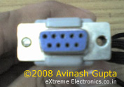
DB9 connector is which connects to your PCs serial Port. Its looks like this.
 |
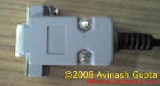 |
A DB9 Connector. |
|
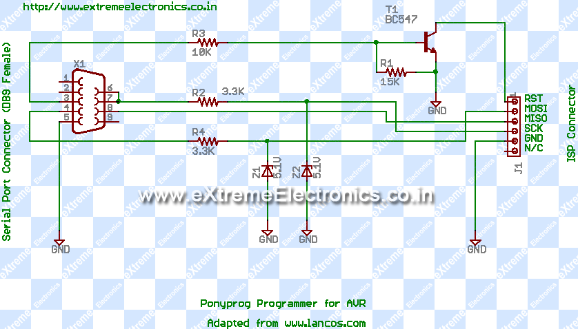
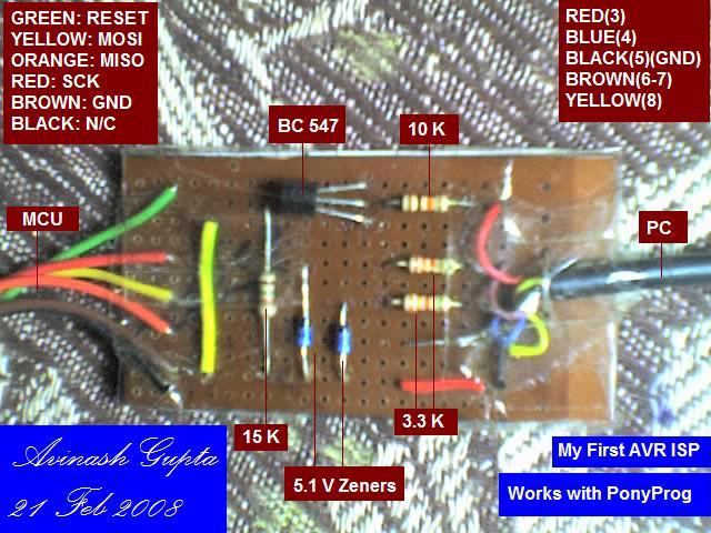
And the 6 Pin connector will make you programmer easy to connect/disconnect from the target board. Now assemble the programmer according to the schematic. Note that the pin numbers are marked on the DB9 connector itself.
|
|
Schematic (Download) |
|
|
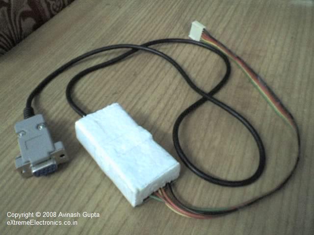
My Prototype |
|
|
Finished with protective cover. |
- RESET(1)
- MOSI(2)
- MISO(3)
- SCK(4)
- GROUND(5)
- NOT-CONNECTED(6)
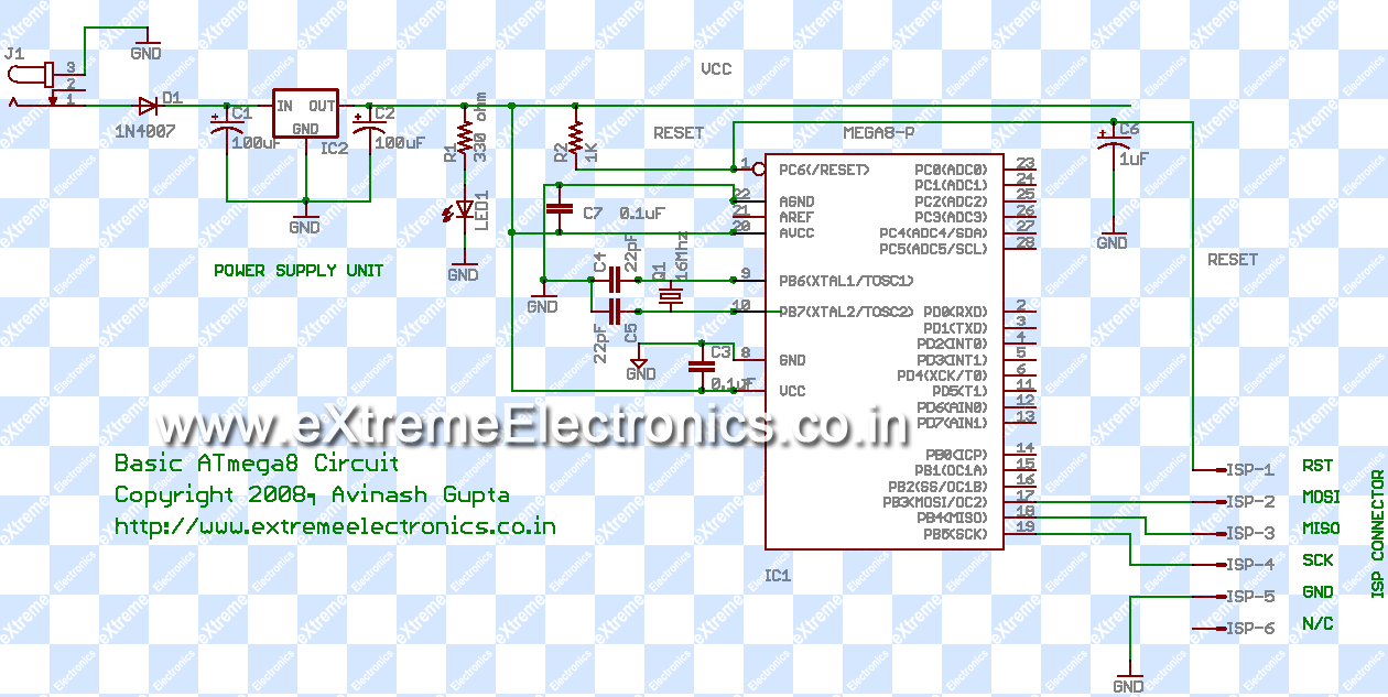
A basic target system
To design a basic target capable of ISP for AVR series of microcontrollers you need to have- Power supply for MCU.
- Crystal Oscillator (for CPU clock)(optional)
- Proper signal at Reset.
- ISP connector
- Aref For ADC.(optional)
Power Supply
Most of the MCUs available works off a 5v power supply except their low voltage versions. They need a clean and stable 5V power supply. This is achieved using the 7805 voltage regulator IC. Also the MCUs have a separate power supply for its analog parts to increase their accuracy and reduce noise. This must not be connected directly with the digital supply but connected via an LC network with the Vcc. You need not care this if you are not going to use the ADC(analog to digital converter) . You can conned AGND to GND and AVcc to Vcc.Crystal Oscillator
This is like a heart for MCU. It provides a beat that makes the MCU take steps. In AVR series of MCU each clock pulse executes one instruction (some instruction needs more than one clock cycle to execute) for accurate timing in you application you need a crystal oscillator. It provides a clean, voltage and temperature independent clock source. Generally,you can use crystals from 1 MHz to 16 MHz on most AVRs as required for your project. Actually the AVR has a internal oscillator also !!! that means this can be omitted. But one limitation is there the internal oscillator provides maximum frequency of 1 MHz if that’s enough for you, then its ok else you have to go for an external crystal of say 12Mhz or 16 Mhz.Reset Signal.
This signal must be high (5V) for normal operation and can be pulled low to reset the device. You can connect a switch to reset the device from it.ISP Connector
For flexibility you should have a nice connector for is so that you can connected/disconnect a programmer easily for programming. The MCU has 3 PINs for the downloading a program in its flash namely • MOSI – Master Out Slave In • MISO – Master In Slave Out • SCK – Serial Clock That’s for date transfer and you also need to connect RESET PIN of MCU to the ISP Connector so that programmer can put it in programming mode. One more pin should be their that is the common or ground of the two system. So all you need is a 5 PIN connector for programming. However, our AVR programmer has one additional PIN that is not connected to any thing so you need a 6 PIN connector in your target system.Aref
This pin must be provided with the reference voltage for the inbuilt Analog to digital convertor. Also this pin is suggest by Atmel to be decoupled with a 0.1uF capacitor. I am providing this in my schematic to be complete. You can omit this if you are not going to use ADC for now. More on these on tutorial on ADC. A basic target schematic
Basic Target for ATmega8 MCU.(Download) |
| S.No |
Name |
Component |
Value |
Qty |
| 1 | IC1 | Microcontroller ATmega8 | 1 | |
| 2 | IC2 | 7805 voltage regulator | 1 | |
| 3 | C1,C2 | Electrolytic Capacitors | 100uF | 1 |
| 4 | C6 | 1uf | 1 | |
| 5 | R1 | Resistor | 330 | 1 |
| 6 | R2 | 1K | 1 | |
| 7 | C3,C7,C8 | Ceramic Disk Type capacitor | 0.1uF | 3 |
| 8 | C4,C5 | 22pF | 2 | |
| 9 | LED1 | LED | 1 | |
| 10 | D1 | Diode | 1N4007 | 1 |
| 11 | Q1 | Crystal Oscillator | 12MHz | 1 |
| 12 | J1 | Power Jack Connector | 1 | |
| 13 | 6 PIN Connector | 1 | ||
| 14 | General Purpose PCBs, wire etc |
You can make the above in general purpose PCBs (Vero board) or in a Breadboard. After making it, double check the connections. Use a socket for the MCU so that it can be easily removable. Then check the voltage levels at the supply pins in the socket with multi-meter. It should be very close to 5 volts.
See Also
Download PDF version| Get Adobe ReaderFree !!!
| Whats next |
| Now you have the basic hardware tools in the next part we will be downloading and installing software tools.WinAVR – A free C compiler for AVRsAVR Studio – The IDE for AVRs from there manufacturer. This will be our front-end for the above compilerPonyprog – A free serial device programmer. |
Facing problem with your embedded, electronics or robotics project? We are here to help!
Post a help request.



Pingback: Home Made AVR Devboard | eXtreme Electronics
Thank you for ur simple circuit solution. I will try out then come back to you.
Thanks K.Asokan
Pingback: PWM Signal Generation using AVR Timers | eXtreme Electronics
It’s the first time I commented here and I must say that you provide genuine, and quality information for bloggers! Great job.
p.s. You have an awesome template for your blog. Where have you got it from?
Do you guys have a recommendation section, i’d like to suggest some stuff
@Lorie,
Sure you can mail me any recommendations
avinash@eXtremeElectronics.co.in
Hi Avinash,
I tried above serial programmer but it not work properly with pony prog.
I want to use this programmer with CodeVision AVR or AVRStudio for direct programming with these IDE what settings required for that.
Good Work,
Waiting for new tutorials,
Kapil
Pingback: DIY AVR Programmers | Embedded
hi avinash
does it work with all the avr like atmega16 , atmega32 ?
YES it works with popular AVRs like ATmega16 , ATmega32 and a dozen others too !!!
hi avinash
when i use it with ponyprog , it is not passing probe test in interface setup
avinash actually i am completely new to this topic that’s why i am getting a bit confused. i have following question for you to answer.
what is an adapter?
in pony prog site they gave different kinds of adpter for different kind of ics of atmel
which site should i visit so that i can learn about these things from scratch?
plz reply soon. soon for the big blog:)
Dear,
I’ve found from another reference, that ISP for ATMEGA series is not working with MOSI MISO, but will working by using Rx Tx pin (PE0 and PE1 on ATMEGA128).
So what is the solution for creating the ISP schematic?
Thanks.
hi avinash,
great tutorials.. very resourceful.
i used the serial isp, avrstudio and ponyprog as indicated by you for serial programming. Moreover i used a usb to serial converter for serial programming from the usb port of my laptop.
The codes are burnt successfully but the verification of the code done by ponyprog while writing takes about an hour to complete..
is this normal?
if not then can you suggest what might be the problem?
please help..
A very common problem. USB TO SERIAL CONVERTERS CANNOT BE USED WITH THESE TYPE OF PROGRAMMERS !!! SORRY
🙁
Get a direct USB Burner from here 🙂
http://shop.extremeelectronics.co.in/product_info.php?cPath=21&products_id=28
We also sell the USB to serial convertors here and WE CLEARLY MENTION THAT IT WON’T BE USED THAT WAY !!!
http://shop.extremeelectronics.co.in/product_info.php?cPath=26&products_id=34
Hi ! avinash, thanks for excellent tutorials. i am using ATMEGA32 and ATMEGA8535 microcontroller.
presently i use internal 1MHz clock , as it is factory preset, but i want to use 12 MHZ external Crystal, what is necessary settings in ponyprog.
I have 3 new ATMEGA32 and due to some wrong settings they are not working how can i use them again.
Please reply me. Waiting for your reply.
thank you.
Hi avinash
today i done same thing with ATMega8535 when i accessing the port B for LED and then connected with LED ant programmed with PONyprog the suddenly all led’s glow then error displayed in ponyprog software “device missing or unknown device(-24)”. please this is my fourth Microcontroller.
how can i make them usable.
thanks in advance.
waiting for your reply.
@kapil see the forum.
Pingback: Avr serial port
I have tried Parallel Port AVR programmer but I failed. I would ask that ir really works? Don’t mean it any other way. I want to know it for my self esteem.
hey im going to build this but I have seen references of this same schematic but without a transistor, I would like to know if its absolutely necessary want to program a atmega8
i tried avr insystem programmer
i using the following config
atmega8, 12 Mhz crystal osc,
its always giving “device missing -24 ” error
were could be the problem. plz reply
i’m trying to connect my progammer with ponyprog, but it doesn’t work…
i made a PCB, it is on this link – http://img43.imageshack.us/img43/2571/plocica.jpg
Can U please tell me if I made any mistake or what, because it doesn’t work…
P.S.
Do I have to make ” A basic target system” and connect it to be able to program or I can do that only with this programmer????
@Cicak
i’m trying to connect my progammer with ponyprog, but it doesn’t work… [ clarify “connect” what do u mean by it]
Can U please tell me if I made any mistake or what, because it doesn’t work…
P.S.
Do I have to make ” A basic target system” and connect it to be able to program or I can do that only with this programmer????
[How Can u program ONLY with this Programmer ???]
Can you please tell me what is wrong with my programmer, because it won’t work…
There is picture, and please tell me if I did something wrong in PCB or what…
Please…
P.S.
Do I need to have DEVBoard to be able to program Atmega8 or just having programmer is enogh…
“How Can u program ONLY with this Programmer ???”
Well, I’m new in programming Atmel, I used to program PIC microcontrollers, and for PIC I found few JDM programmers that are very simple, so I thought that this is similar but just for atmel…
I didn’t know that I have to make devboard also and connect it with programmer to be able to program atmega8…
Can You please send Your PCB layout of devboard to email, so I can make one at home…
Can I connect a serial programmer to USB port using USB to serial converter
I have made this one to program an ATMEGA8L. Using ponyprog read operation is successfully done.But when I tried to write, program is verified after writing and at last “Write failed” is shown. then I have read it again but it shown 00 as a hole. Also the read write operation is very slow.can u help me to make a successful and faster read write operation?
Does this is the exact Programmer found in the shop of extreme electronics.
Can I monitor clock frequency at pins 9 or 10 of ATMEGA8?.
I have tried to probe with a osciloscope but could not see ant trace. How to find that The chip is runnung at the crystal frequency?
Hello Avinash,
Thanks for the informative tutorials. They should be really helpful for any newbie.
However, In this Serial programmer circuit, I think there should be a connection form the +5V supply of the uC to the collector of the BC547.
please refer to this circuit: http://electronics-diy.com/avr_programmer.php
Hope this helps..
In appreciation
Biswarup Mukherjee
I have followed step by step the tutorial and…It works!!
I have been able to flash easily an Atmega8 with this programmer.
My two cents: be careful, don’t use long cables or It won’t work!
sir
nice circuit
i m using atmega8L do i have 2 give a clock of 8 mhz
Sir,
You have explained making a programmer using Atmega8.In that you have connected crystal oscillator with the pins PB6(XTAL1/TOC1) and PB7(XTAL2/TOC2).But I want to use Atmega32.The problem is that in Atmega32 pins XTAL1 ,XTAL2 ,TOC1 and TOC2 are separate.so can you please tell me to which pins i’ve to connect this crystal oscillator.Please reply .its urgent i’m making that project.
XTAL1, XTAL2 r the pins to which crystal oscillator is to be connected. pls read datasheet before doing anything. also u need to add capacitors as mentioned in datasheet. make sure that the oscillator connection leads are as small as possible and near to the mcu.
i did this project. so mail for any doubts.
akhil423@gmail.com
If I need to use ADC in Atmega8,do I need to connect another 10uH of inductor between Vcc and AVcc? I read the datasheet of Atmega8 and it says that I need to connect 10uH inductor and 0.1uF capacitor.Actually,this is stated in this tutorial too in the part ‘Power Supply for MCU’ under the topic ‘A Basic Target System’.It stated that AVcc need to connect via an LC network with Vcc.So, am I right that I need to connect one more inductor cauz in the schematic diagram, I’ve found the 0.1uF is connected but I can’t find any inductor there.
Besides that, do I need other connection of components due to my need to use the ADC in Atmega8?
Thanks for reply.
Pingback: Firefox Bookmarks « Rabiul's
THANKS AVINASH FOR PROVIDING SUCH A USEFUL INFORMATION. I WAS SEARCHING FOR IT FOR A LONG TIME….
Hi
Actually the maximum frecuency for the internal oscillator is 8 MHz. Check the clock options in the uc datasheet. Great tutorials btw!
heelo
can i use a pcmcia to serial adaptor to program the AVR?
thank you
@Ahmad,
Why do such weird things? If low cost USB AVR Programmer are available through out the world. Even very easy to make? Serial Port Programmers are damn slow even when run from a real serial port!
Pingback: programer supoport for at89s52
Hi friends
If ur having PC with windows xp and parallel port then u can have programmer in less than Rs.100/- [INR].
[Make sure that PC is installed with Windows XP and has parallel port]
Here is all help u need to built programmer-
http://embeddedelectronicsforatmegaseries.blogspot.com/
If u saw the connectors SV1 and SV2 carefully,they are 6 pin connectors.It can be managed with 5 pin connectors also. just remove NC[No connection] pin of 6 pin connectors.
Sequence of the 6 pin connector[as shown in fig.]
MOSI
MISO
SCK
/RST
NC[No connection]
GND
Sequence of the 5 pin connector[after removing NC pin]
MOSI
MISO
SCK
/RST
GND
this is it.
if there are any queries then post it to blog
@Kaustubh,
Its like hunting dodos for lunch, why not buy chickens!
Parallel ports are damn slow when used for programming ATmegas! and are more rare than dodos.
http://en.wikipedia.org/wiki/Dodo
@ Avinash,
Hey !!
I use to hunt Dodos for lunch.
You can come to my place & we can Njoy “LUNCH” together.
🙂
Hi,
I need a help!!
I don’t have a serial port in my laptop…!! My friend accidentally got the burner with the above circuit.. So i bought a usb to serial converter and connected the circuit.. Then i downloaded the pony prog software. The probe test gave ok but then when i gave the write option it says device missing…..Can anybody help me out with this???
@Vignesh
You just lost your money. This does not work with USB to Serial Converters!
@Vignesh
See coment number 16
https://extremeelectronics.co.in/avr-tutorials/part-iii-making-programmer-and-target/comment-page-1/#comment-2024
thanks.thanks.thanks.
Thanks for the circuit..
Hi, i have already purchased your AVR Programmer in the past, now i want to purchase your AVR low cost development board, can you please clarify for me one thing please?
Will i be able to connect the ISP cable from programmer to development board directly? i mean is there appropriate socket? this has always been a problem for me because my target circuit was on a breadboard and i could not conect the isp calbe properly
@Prithviraj Nag
Yes if you have v2.0 of USB AVR Programmer then it mates nicely with 40 PIN DEV Board.
Sir
you did a good job
i have build a similar programmer
this is a serial port avr programmer
http://microembeded.blogspot.com/2011/04/avr-serial-port-programmer.html
i will provide live support for the programmer
thanks, i was looking for avr programmer circuit.
Hello !!
Can i use with with Atmega128 (like AT90CAN128). If not, can you suggest me some other way to upload the program into the chip instead of buying ready made development board.
Please reply !!
Pingback: atmega 32 serial programmer
can it program the at mega 328 ?
i am quite new to this,
would it be a problem if i use 16mhz crystal instead of the given 12mhx one?
Hey!
Actually we need to make programmer using serial port using Labview..
so do u have any idea??
plz reply to this thread..
can i program AT89S52 MCU with this programmer
@Narendra,
No!
using AVR icsp programmer.
which software is to program AVR
waiting for you reply
Pingback: DIY AVR Programmers | Engineers Connect
Dear Avinash,
270 ohm resistors in MOSI, MISO and SCK lines?
Is it a good idea to add these ?
Regards.
Karanbir
Hi Avinash, Is this ISP Programmer hardware works with extremr burner software,