Now you have the basic hardware tools, its time to setup the software environment.The main software you will need are:
- AVR Studio – A GUI IDE for AVR(www.atmel.com, http://www.atmel.com/dyn/resources/prod_documents/AVRStudio4.13SP2.exe)
- WinAVR – a free C compiler for AVRs (http://winavr.sourceforge.net/download.html)
- PonyProg – Serial Device Programmer (www.lancos.com)
Step I Entering and compiling code.
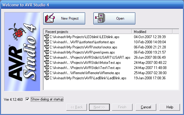
Start “AVR Studio” from Start Menu->All programs->Atmel AVR Tools-> AVR Studio 4 You will be presented with a Project wizard as shown below.|
|
Fig – AVR Studio Project Wizard |
|
|
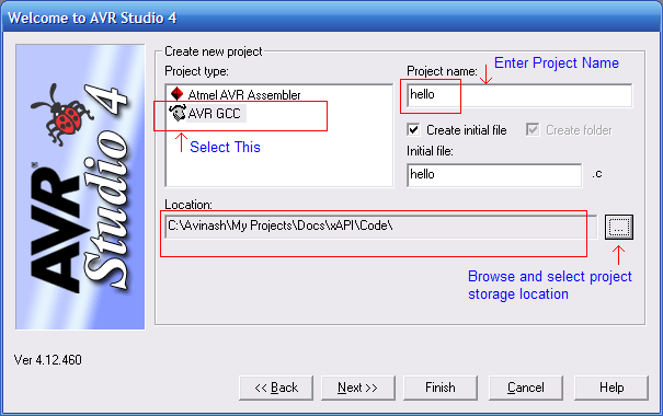
Fig – Project Details |
|
|
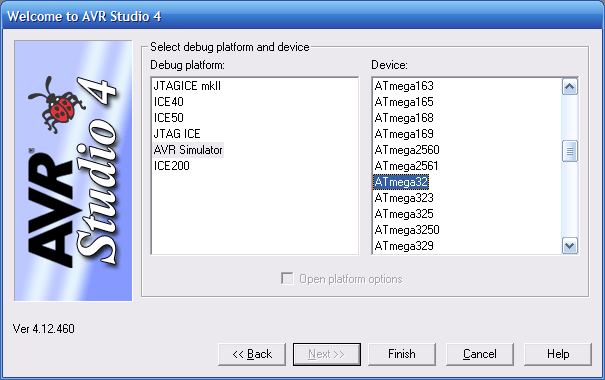
Fig – Device Selection |
| |
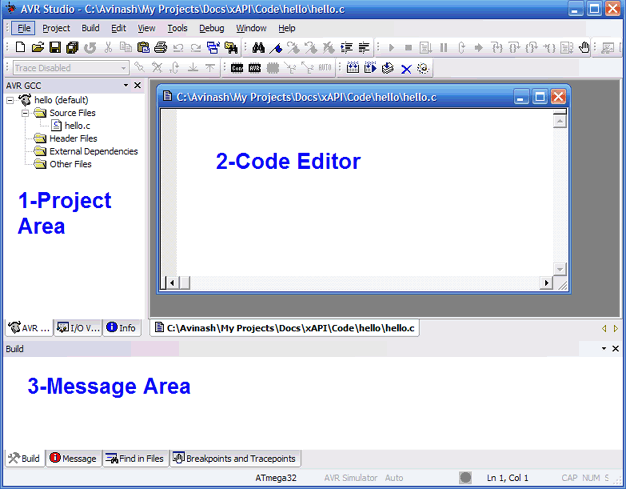
Fig – AVR Studio main window |
-
Project Area – displays all the files source and header in the current project. You can add and remove files by the context menu of different groups like “source file” , “header files” etc. Double click a file to open it in the editor.
-
Code Editor – Here you enter and edit the files.
- Message Area – Here AVR Studio will show errors and warning generated by compile when it tries to compile a source file.
#include <avr/io.h>
#include <util/delay.h>

void Wait()
{
   uint8_t i=0;
   for(;i<23;i++)
      _delay_loop_2(0);
}

void main()
{
   //Set PORTC0 as output

   DDRC=0b00000001;

   while(1)
   {
      //Set PC0=High(+5v)
      PORTC|=0b00000001;
      Wait();

      //Set PC0=Low(GND)
      PORTC&=0b11111110;
      Wait();
   }
}
If you don’t understand the program don’t worry, the next tutorial will teach you how to setup and use general purpose IO ports in AVR.
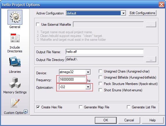
Go to Project->Configuration Options to bring the Project option dialog.
|
|
Fig – Setting CPU frequency and compiler optimization |
Fig – Message |
|
|
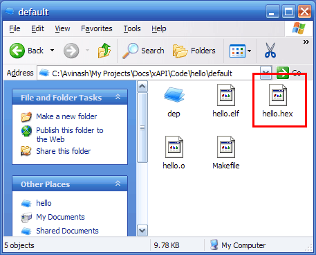
Fig – Finding “hello.hex” file |
Step II Programming the MCU with “hello.hex”.
Now its time to burn this hex file to your MCU. To know how to burn the hex file to you MCU refer to you programmers manual. You can use eXtreme electronics USB AVR Programmer to burn hex files to you mcu (see shop section). Detailed procedure is given in “programmer” folder in its support CD.Programming Using PonyProg.
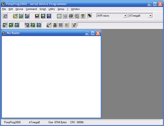
This is the programmer we made in the previous tutorial. Its use is simple. Start Ponyprog, you will get a screen similar to this.|
|
Fig – Ponyprog main window. |
|
|
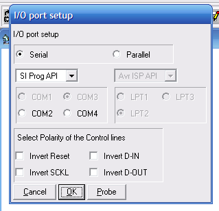
Fig – Ponyprog Setup |
- Select the hex file you want to program using the File->Open Program(FLASH) file.
- Command->Erase.
- Command->Write Flash
- Command->Verify Program(FLASH)
- If every thing is correct, your MCU is programmed successfully.
- Disconnect programmer from the Target and switch it off.
Step III Electrical Connections.
This is a very simple project you don’t need any complicated connection.You may be using any of our development boards like xBoard™, xBoard™ MINI or simpler xCards™. You just need to figure out where is the MCU ports (which is programmed to blink LED, in this case PORT C’S 0TH BIT) connector on the board. They are clearly marked in the boards. After finding it, connect the LED as follows to the MCU port .Or you can make your own target boards as explained in previous tutorials. I am not showing all the connection here because I have already shown in previous tutorials.|
|
Fig – Connecting a LED. |
The VCC (5v) required is also available in the board and marked as “spare 5V” or something like that. After all connections connect power supply (make sure the polarity is correct) to the board and switch on. The power indicator LED of board should glow and the LED connected to the MCU’s port should blink on and off. Now you can relax and enjoy than light blinking with all that modern sophisticated technology behind it and you first dedicated embedded program doing all the magic.
Now go on with your imagination tweak the program, modify delay and switching logic to get interesting patterns blinking. The limit is your imagination.
Note |
| Note: For More information on using AVR studio see AVR GCC Plugin Help in the Help Menu |
Download PDF version | Get Adobe Reader Free !!!
What’s next |
| Next we will learn about the GPIO ports, i.e. the General Purpose IO ports. They are the most fundamental type of interface between MCU and real world. |
Facing problem with your embedded, electronics or robotics project? We are here to help!
Post a help request.




Pingback: Using IR remote with AVR MCUs - Part II | eXtreme Electronics
Pingback: AVR Project – Relay Timer with ATmega8 AVR MCU | eXtreme Electronics
Pingback: Sound Generation by AVR Micro - Tutorial I | eXtreme Electronics
hi there,
i am new in AVR programming… these tutorials are really helping me a lot to understand the basics of AVR.
well, lets come to the point, in the above program “uint8_t” is used for the data type of variable “i”. as i said before, i am novice, so can you please explain what is the difference between a regular data type and “uint8_t” or “uint16_t”
thank you
Pingback: Interfacing MMA7260 Triple Axis Accelerometer with ATmega32 - AVR Tutorial | eXtreme Electronics
Pingback: Interfacing Graphical LCD with AVR MCU - Part II | eXtreme Electronics
Pingback: 4x3 4x4 Matrix Keypad Interface with Atmel AVR Microcontrollers | eXtreme Electronics
Hi Avinash,
I need one info from you..
If you have any idea about RF tx & rx which can support distance >200-500m.
please let me know…
Iam in urgent requirement of that for my new project.
Thanking in anticipation.
Regards,
Manu
@Manu
Check out this 1KM module
http://aplusindia.net/aplusindiauser/ProductDetailAction.apu?prodno=SM-TR1100-TR&cat_id=52
Also from next time please use the forum for discussion.
http://forum.extremeelectronics.co.in/
Pingback: Handling Text and Fonts in ProGFX | eXtreme Electronics
The publish is in reality the great on this worthy subject. I match in together with your conclusions and looking out ahead to your coming updates. Simply saying many thanks won’t simply be enough, for the fantastic readability inside your writing. I’ve grabbed your rss feed to remain knowledgeable of any updates. Gratifying work and much achievement in your corporation dealings!
Pingback: AVR Project – ATmega8 based RMP Meter | eXtreme Electronics
Pingback: Interfacing Ultrasonic Rangefinder with AVR MCUs | eXtreme Electronics
Dear Mr. Avinash
Your tutorials are really great.
I am trying to install WinAVR and AVR studio as you mentioned in tutorial_4. but after installing winAVR-20100110-install, when i try to install AVR Studio4.13sp2 an warning message
“AVR Studio 4.13 must be installed”
is showing.
Would you please suggest me what should I do?
Shahin
Pingback: AVR Project – ATmega8 Based Smart Code Lock | eXtreme Electronics
hi avinash i need your help urgently …my avr studio hangs on compling and shuts down… i tried reinstalling the software as also tryin an updated version but still the problem persists..
Pingback: Analog Clock on GLCD – Drawing the Face | eXtreme Electronics
How do I know what frequency value should I enter in the frequency box. It has to be different for different boards.
hai avinash,
AVR programmer was not available here .it will take days to get the programmer.so our professor gave us a circuit for programmer.we are soldering it now.can you tell me about fuse bit settings and how to do it.we are doing with a 12mhz frequency.what is the fuse bit settings for it and how will we set it.first we set separately one by one
then avr became locked.2nd time we did it simultaneously then error was shown.can you help me please?
@Vishnu,
Why don’t you ask your “professor” who is guiding you. Coz he gets paid for that !
I am not so educated.
Pingback: Using LCD Module with AVRs | eXtreme Electronics
Very good site of information and best priced goods.
The writer should be thanked..
Explained in very simple language with Microwave appliance.
my elf file is not getting generated. what do i do?
May I ask you a basic question, here no external crystal is used , means internal oscillator of microcontroller is used, what is the frequency of this oscillator, You write
uint8_t i=0;
for(;i<23;i++)
_delay_loop_2(0);
So how many millisecond or microsecond for number 23,how this number is related to internal frequency of microcontroller and desired delay time, how this calculation done
Regards,
Uttam Dutta
_delay_loop_2(n);
burns 4 CPU cycles for each n.
For example n=1 will burn 4 CPU cycles.
n=2 will burn 8 CPU cycles
argument n is of type 16 bit unsigned integer.
So it can be from 0 to 65535.
since passing 0 to a delay function is useless so they made it to represent value 65536 (2^16)
so _delay_loop_2(0); will burn 4 x 65536 = 262144 cycles.
and for(;i<23;i++) will repeat this 23 times = 262144 = 6,029,312 cycles.
Hi Avinash,
Thanks for putting this content together. I am really new to embedded programming. My question is if AVR Studio and Atmel Studio are the same IDE.
AVR Studio is now renamed as Atmel studio
hello i am working on digital voice recorder avr application note 335 i am using the vmlab and winavr gcc compiler but when i run the program it will give the error i got confused when i tried sample source code on atmega8 for led blink application it will run and hex file is generated i have USBisp programmer which support avrbascom extreme and avrdude but i want to use winavr gcc and avr dude to burn the same i surfed on net most people preffered avr studio 4 i have atmel studio 7 which will be the better solution plz guide me……ASAP
Really great work. I tried and it works
Hi Avinash
I am not using an xboard. I connected the programmer directly to atmega8Apu using a breadboard. What frequency should I set. Moreover when I click the build it shows build started but its not proceeding further.
Thanks in advance
Avinash
so many thanks for these instructions. Any idea why your Wait() routine takes my AtMega8 about 5-6 seconds to execute on a 16MHz crystal? Based on bibliography for _delay_loop_2(0) and on your responses to other people’s comments that should work out to ~1/2 second intervals, for this particular tutorial, right? However my cct takes about 10 times that. Am I missing something here?
My circuit is built on a breadboard, if that counts for anything, but the circuit is identical to your schematics (i.e. cap sizes etc.)
Thanks