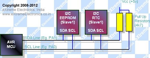
Inter IC Communication or I2C is a two wire serial communication bus used to connect a variety of external peripheral with a microcontroller. Most common are EEPROMs, RTC, Port Expanders etc. Most leading MCUs comes with at least one dedicated I2C host adaptor built in. But some times we need more than one I2C interface or we need I2C lines on some other i/o pins than those allotted to the hardware I2C, in that case we need to go with a solution called SoftI2C. In SoftI2C the I2C signals are handled in software, the advantage is that any two i/o line of the MCU can be used for communication. The drawback is that it need more CPU cycles are wasted in generating the signal thus less time slice is available to the application.
In this article we will present our open source, flexible and easy to use SoftI2C library. This library can be used to connect any I2C slave device with an AVR (and latter PIC MCU) MCU. Some limitations of the library are :-
- No Multimaster support.
- No clock stretching support.
But you can connect multiple number of I2C Slaves on the same bus.
 |
I2C Master/Slave Connection |
The Soft I2C Library for AVR
The soft I2C library for AVR comes in two files.
The configuration section lets you choose the I/O lines used for SDA and SCL. You can edit the i2csoft.h file’s I/O Configuration area to do that. The library can be compiled for almost any AVR device like ATmega8,ATmega168,ATmega328 etc.
API Reference.
SoftI2CInit() Description: |
SoftI2CStart() Description: |
SoftI2CStop() Description: |
SoftI2CWriteByte() Description: |
SoftI2CReadByte() Description: |
In next tutorial I will show you how to interface a I2C EEPROM, Temperature Sensor, RTC, Port Expander etc using our Soft I2C library.
Download
Help Us!
We try to publish beginner friendly tutorials for latest subjects in embedded system as fast as we can. If you like these tutorials and they have helped you solve problems, please help us in return. You can donate any amount as you like securely using a Credit or Debit Card or Paypal.
We would be very thankful for your kind help.
By
Avinash Gupta
Facebook,
Follow on Twitter.
www.AvinashGupta.com
me@avinashgupta.com
Facing problem with your embedded, electronics or robotics project? We are here to help!
Post a help request.


Pingback: 24CXX I2C EEPROM Interface using SoftI2C lib | eXtreme Electronics
Pingback: DS1307 I2C RTCC Interface using SoftI2C lib | eXtreme Electronics
can u tell us the basics of developing codes for three axis accelerometer as early as possible…….
while((SCLPIN & (1<<SCL))==0);
why this is nececery in write byte section in code??
I think this line is for clock stretching… when the slave device is not ready for another clock cycle it holds the clock and so this while loops waits for it.
This software is like other ones? With intended errors?
It’s an rhetorical question, you don’t need to answer.
continuous reading bytes from a slave (e.g. PCF8583 RTC) does not work because of a software-bug in the library:
After performing the read-ack. the AVR does not release the SDA-wire.
Therefore an additional
” SOFT_I2C_SDA_HIGH;” is necessary after the reading routine finished:
uint8_t SoftI2CReadByte(uint8_t ack)
{
uint8_t data=0x00;
uint8_t i;
for(i=0;i<8;i++)
{
SOFT_I2C_SCL_LOW;
H_DEL;
SOFT_I2C_SCL_HIGH;
H_DEL;
while((SCLPIN & (1<<SCL))==0);
if(SDAPIN &(1<>i);
}
SOFT_I2C_SCL_LOW;
Q_DEL; //Soft_I2C_Put_Ack
if(ack)
{
//H_DEL;
SOFT_I2C_SDA_LOW;
}
else
{
SOFT_I2C_SDA_HIGH;
}
H_DEL;
SOFT_I2C_SCL_HIGH;
H_DEL;
SOFT_I2C_SCL_LOW;
H_DEL;
SOFT_I2C_SDA_HIGH; // was missing!!
return data;
}
I was expecting that. I never test this soft but i want to use it. Henry plese can you confirm if it works with the new modifications.
I testet the lib with PIC(MPLab) and AVR(WinAVR) together with a I2C Realtime Clock and it works.
But I dont like the waitstates
therefore better generate a waitstate timer-interrupt and process the bitbanging in a “statemachine”
Hi Henry,
I still do not get the line:
if(SDAPIN &(1i); by doing this the data value remains unchanged. Or am I wrong? I saw that you tested in the previous comment, but I do not observe where the data variable is chnaged from 0.
Thanks
Please look in the original code of the library. the code that i posted is corrupt. some lines are mssing or are corrupt or changed. maybe a problem of this blog software.
if(SDAPIN &(1<>i);
}
ok again the line that you mentioned is corrupted while trying to re-posting it. maybe a problem of the font ? I tried to post it but again some lines are cut out. so better look in the library code of Avinash.
hey henry thanks for your comment, it saves my lots more time
There is another bug in receiving data. In orginal code there is no possibility to receive value 0x7f from i2cbus – there is a problem in SCL line, which should be changed after ack bit. IMHO it should look as follows. Let me now, if it works in continous reading
uint8_t SoftI2CReadByte(uint8_t ack)
{
uint8_t data=0x00;
uint8_t i;
for(i=0;i<8;i++)
{
SOFT_I2C_SCL_LOW;
H_DEL;
SOFT_I2C_SCL_HIGH;
H_DEL;
while((SCLPIN & (1<<SCL))==0);
if(SDAPIN &(1<>i);
}
if(ack)
{
SOFT_I2C_SDA_LOW;
}
else
{
SOFT_I2C_SDA_HIGH;
}
H_DEL;
SOFT_I2C_SCL_LOW;
Q_DEL; //Soft_I2C_Put_Ack
SOFT_I2C_SCL_HIGH;
H_DEL;
SOFT_I2C_SCL_LOW;
H_DEL;
return data;
}
can i use this libraries or header files in programmers notepad?
I can not understand how the read works. DDR register is never changed to input for SDA. AVR uC pins are not open collector/drain but push pull. Before reading SDA pin must be changed to input. In case the master SDA remains HIGH and slave pulls SDA low there will be damage on both pins for sure.
wladimir, please read the other functions of the library and learn how i2c works.
I checked INIT function.
void SoftI2CInit()
{
SDAPORT&=(1<<SDA);
SCLPORT&=(1<<SCL);
SOFT_I2C_SDA_HIGH;
SOFT_I2C_SCL_HIGH;
}
PD0 is SCL
PD1 is SDA
1. You make PD0 and PD1 outputs.
2. Drive both high.
Then I checked Read function.
uint8_t SoftI2CReadByte(uint8_t ack)
{
uint8_t data=0x00;
uint8_t i;
for(i=0;i<8;i++)
{
SOFT_I2C_SCL_LOW;
H_DEL;
SOFT_I2C_SCL_HIGH;
H_DEL;
while((SCLPIN & (1<<SCL))==0);
if(SDAPIN &(1<>i);
}
…
You do a clock signal on SCL by:
1. Driving SCL low.
2. Driving SCL high.
Then you loop while SCL (PD0) until it is high.
In other words when it becomes low stop loop and read SDA.
My major thought:
You never changed SCL and SDA to be inputs.
How do you read from PD0 and PD1 since they are OUTPUTS ?
The Library doesnt change the output port to low and high. The Library changes just the DDR to switch between input/high by pullup and low and not the PORT Register. Therefore the output port has to be initialized to always “0”
#define SOFT_I2C_SDA_LOW SDADDR|=((1<<SDA))
#define SOFT_I2C_SDA_HIGH SDADDR&=(~(1<<SDA))
#define SOFT_I2C_SCL_LOW SCLDDR|=((1<<SCL))
#define SOFT_I2C_SCL_HIGH SCLDDR&=(~(1<<SCL))
how to interface a 6 axis GYRO(521)-MPU-6050 using i2c.
tell me how to read the values using programmers notepad.
Tell me your credit card number and PIN
can this library do 14 bit of data from a sensor,if so please show how it is done.
In init:
SDAPORT&=(1<<SDA);
SCLPORT&=(1<<SCL);
____
Did you miss "~" there?
If not then what the point of it? Reset all other pins of port to 0? But what if there other peripherials?
And if you drive by internal pullups, why SOFT_I2C_SCL_LOW/HIGH changes the DDR but not PORT?
thank u it helped alot