Many project requires some kind of Audio output. For example a burglar alarm, an automated school bell or simple electronic games or even a robot! In Old days we used some some dedicated Music and Audio Effect chip to do that. At that time ICs such as UM66 were very popular. Now in the days of microcontrollers, a good design is to use least number of external components to get the job done. So if you still use external audio ICs with a MCU based design then your design is inefficient and costly. The smart idea is to get most of the job done in software. In this article we will learn step by step how to produce different kinds of audio effect by just using an AVR MCU and A speaker. After reading this you would be able to provide simple sound output in many AVR based projects. So lets get started!
I will start this series with a direct runnable example so that you can burn it into an AVR and see how it sounds! In latter parts I will elaborate how this was achieved. Some techniques that were used to achieve audio generation are.
- PWM or Pulse width modulation: It is a technique to generate analog voltage levels by a digital device (say a MCU). Generally a digital device can only generate HIGH or LOW level signals on their I/O Ports. But a using PWM we can generate any analog voltage level on MCUs PORT, for example we can generate any voltage between 0 and 5 volts like 2.67v or 1.11v etc. Refer to following tutorials for more information on PWM
- Sine wave generation: All musical tones are sine wave of some frequency.
- Program Space Strings: Sine table used to generate sine wave is stored in flash memory. Knowledge of program space string in avr-gcc is necessary.
Hardware
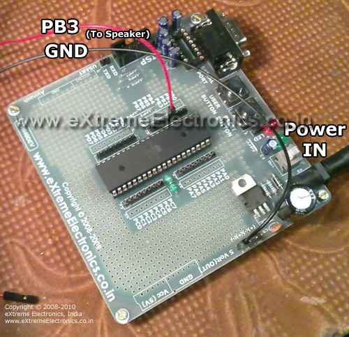
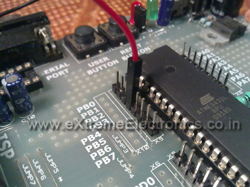
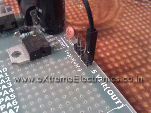
The hardware is ATmega32 running at 16MHz. I used the Low Cost AVR Development board to run the demo. Just hook a small (about 1 or 2 watt ) 8ohm speaker between PB3 and GND and you are ready. Those who don’t have the Low Cost AVR Development board may buy it from our online shop or build it at home as described here. The fuse bytes must be programmed as HIGH FUSE=C9 LOW FUSE=FF.
AVR 40PIN Low Cost Development Board Schematic |
 |
Connecting a Speaker |
 |
PB3 |
 |
GND |
 |
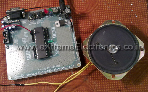
Whole setup for simple sound generation with AVR MCU. |
Software
The software is written in C language and compiled using the avr-gcc. AVR Studio was used as a front end to avr-gcc. More details on compiling project is here.
File Name: pwmsnd.c
/********************************************************************

DESCRIPTION:   A Simple program to genarate some random

            musical tone.

MCU:        Atmel AVR ATmega32s

CPU SPEED:     16Mhz

LOW FUSE:      0XFF
HIGH FUSE:     0XC9

NOTE:       Connect a 8ohm speaker between GND and PB3.


AUTHOR:        Avinash Gupta
DATE:          Mar 18, 2010

WEB:        www.eXtremeElectronics.co.in


*** THIS PROJECT IS PROVIDED FOR EDUCATION/HOBBY USE ONLY  ***

*** NO PROTION OF THIS WORK CAN BE USED IN COMMERIAL       ***
*** APPLICATION WITHOUT WRITTEN PERMISSION FROM THE AUTHOR ***

EVERYONE IS FREE TO POST/PUBLISH THIS ARTICLE IN
PRINTED OR ELECTRONIC FORM IN FREE/PAID WEBSITES/MAGAZINES/BOOKS
IF PROPER CREDIT TO ORIGINAL AUTHOR IS MENTIONED WITH LINKS TO
ORIGINAL ARTICLE

COPYRIGHT (C) 2008-2010 EXTREME ELECTRONICS INDIA.

*********************************************************************/


#include <avr/io.h>
#include <util/delay.h>
#include <avr/pgmspace.h>

#include "sin.h"

/*

Function To Initialize TIMER0 In Fast
PWWM Mode.

*/
void InitPWM()
{
   /*
   TCCR0 - Timer Counter Control Register (TIMER0)
   -----------------------------------------------

   BITS DESCRIPTION

   NO:   NAME   DESCRIPTION
   --------------------------
   BIT 7 : FOC0   Force Output Compare [Not used in this example]
   BIT 6 : WGM00  Wave form generartion mode [SET to 1]

   BIT 5 : COM01  Compare Output Mode        [SET to 1]
   BIT 4 : COM00  Compare Output Mode        [SET to 0]
   BIT 3 : WGM01  Wave form generartion mode [SET to 1]
   BIT 2 : CS02   Clock Select               [SET to 0]
   BIT 1 : CS01   Clock Select               [SET to 0]
   BIT 0 : CS00   Clock Select               [SET to 1]

   The above settings are for
   --------------------------
   Timer Clock = CPU Clock (No Prescalling)
   Mode        = Fast PWM
   PWM Output  = Non Inverted

   */


   TCCR0|=(1<<WGM00)|(1<<WGM01)|(1<<COM01)|(1<<CS00);

   //Set OC0 PIN as output. It is  PB3 on ATmega16 ATmega32

   DDRB|=(1<<PB3);
}

void main()
{
   uint8_t i;

   InitPWM();

   while(1)
   {

      uint8_t delay,n;

      for(delay=1;delay<=50;delay++)
      {
         for(n=0;n<(51-delay);n++)
         {
            for(i=0;i<=254;i++)
            {
               OCR0=pgm_read_byte_near(sine+i);
               _delay_loop_2(delay);

            }
         }
      }
      for(delay=50;delay>=2;delay--)
      {
         for(n=0;n<(51-delay);n++)
         {
            for(i=0;i<=254;i++)
            {
               OCR0=pgm_read_byte_near(sine+i);
               _delay_loop_2(delay);
            }
         }
      }

   }
}
File Name: sin.h
#include <avr/pgmspace.h>
prog_uint8_t sine[256]={
127,
130,
133,
136,
139,
143,
146,
149,
152,
155,
158,
161,
164,
167,
170,
173,
176,
178,
181,
184,
187,
189,
192,
195,
197,
200,
203,
205,
207,
210,
212,
214,
217,
219,
221,
223,
225,
227,
229,
231,
232,
234,
236,
237,
239,
240,
242,
243,
244,
245,
246,
248,
248,
249,
250,
251,
251,
252,
253,
253,
253,
254,
254,
254,
254,
254,
254,
254,
253,
253,
253,
252,
252,
251,
250,
250,
249,
248,
247,
246,
245,
243,
242,
241,
239,
238,
236,
235,
233,
231,
229,
227,
225,
224,
221,
219,
217,
215,
213,
210,
208,
206,
203,
201,
198,
195,
193,
190,
187,
185,
182,
179,
176,
173,
170,
167,
164,
161,
158,
155,
152,
149,
146,
143,
140,
137,
134,
131,
128,
125,
121,
118,
115,
112,
109,
106,
103,
100,
97,
94,
91,
88,
85,
82,
79,
76,
73,
71,
68,
65,
62,
60,
57,
55,
52,
50,
47,
45,
42,
40,
38,
36,
34,
31,
29,
27,
26,
24,
22,
20,
19,
17,
15,
14,
13,
11,
10,
9,
8,
7,
6,
5,
4,
3,
3,
2,
2,
1,
1,
0,
0,
0,
0,
0,
0,
0,
1,
1,
1,
2,
2,
3,
4,
4,
5,
6,
7,
8,
9,
10,
12,
13,
14,
16,
17,
19,
21,
22,
24,
26,
28,
30,
32,
34,
36,
39,
41,
43,
45,
48,
50,
53,
55,
58,
61,
63,
66,
69,
72,
74,
77,
80,
83,
86,
89,
92,
95,
98,
101,
104,
107,
110,
113,
116,
119,
122,
};
HEX File for Simple Sound Generation with AVR.
AVR Studio Project for Simple Sound Generation with AVR.
Request to Readers
Tweak the sound generation algorithm, timing, loops etc to create your own masterpiece. And don’t forget to upload it to Youtube and mail me the link I will post it here !
Video
A live demo ! So lets see how it sounds !
Facing problem with your embedded, electronics or robotics project? We are here to help!
Post a help request.


please explain how you have generated the sound wave
and about sinwave generation
with best wishes
This is very good and usefull project work which reduce the hard ckt used for alarm.
thanks
Can we produce some speech sound using PWM?
Could you explain what “pgm_read_byte_near(sine+i)” does in the above code?
can i know the funda of the code pls??
or suggest material that is sufficient to learn this completely!!
thanks~~
To produce speech, you would require quite huge memory. Just check out this link, it explains clearly.
http://avrpcm.blogspot.com/2010/11/playing-8-bit-pcm-using-any-avr.html
GREAT!! it works on my ATMega 8535 with winavr.. thx dude..
Hello,
I have a team project assignment in which the first part of the project is to produce 8 different sine waves. I’m having to use the ATmega88, will it be possible with that ?
The next part of it would be to record the sound using a microphone and then displaying that on a LCD. All of this must be achieved by a single microcontroller so will the ATmega88 suffice ?
Thanks
Do not drive a speaker directly from the microcontroller like this. If the impedance of the speaker is 8/16ohms, it will consume too much current from the AVR port, and may permanently damage it.
Pingback: Problem in Generating Audio from AVR ATmega 32 micro-controller using PWM.
I liked the project, but my requirement is little different. I want to play live sound by receiving samples through UART. Can you give me some suggestions on how to implement this. I am creating two buffers and being able to get the data from UART but the sound play quality is completely different, there is lot of hisses in the audio file.
I am also using PWM for audio generation on STK600 where my file is sampled at 3906.25Hz and playback code is also for same PWM frequency. I receive audio properly but I get noise in background too. It remains there as long as file is playing. The speaker is connected directly between PWM output pin and ground. Do I need to connect any filtering circuit?? And fuse register values are Low 0xE2, High 0x99 and Extended 0xFF do I need to change those values??
Instead of mapping out each individual value, I usually use half of the parametric equation for a circle to generate my sine waves:
/*
The following generates successive values of a sine wave between 0 and 255, via
x = radius * cos(radians) + offsetX
or
y = radius * sin(radians) + offsetY
Either equation will generate a sine-type wave within the proscribed values, the difference being only in phase.
*/
int i=0;
int value;
double radius = 255; // The range of the wave
double offset = 128; // The offset from 0 of the wave.
while(i++) {
value = radius * sin( (double) i * M_PI / 180.0 ) + offset;
doSomethingWithValue(i);
}
@Franz, sin cos calculations are very slow on 8 bit MCU. Thats why they are precomputed and stored.